
Overview: The Role of CO₂ Compressors in Carbon Capture and Storage
Carbon capture and storage — widely abbreviated as CCS — is the process of capturing carbon dioxide from large industrial point sources, transporting it, and permanently injecting it into deep geological formations where it cannot contribute to atmospheric warming. When the captured CO₂ is used productively before or instead of storage — for example, to enhance oil recovery or to produce synthetic fuels — the broader term carbon capture, utilisation, and storage (CCUS) applies. Both pathways share the same fundamental engineering challenge: CO₂ captured at near-atmospheric pressure from a flue gas or process stream must be compressed to supercritical injection pressure, typically 15 to 32 MPa, and maintained at that pressure throughout the pipeline transport and wellhead injection system.
The CO₂ compression system is the single largest energy consumer in a CCS chain, accounting for 20 to 40 percent of the total parasitic power load of the capture plant. It is also one of the most technically demanding unit operations, because it must handle a gas that behaves unusually near its critical point, that may contain corrosive impurities depending on the capture technology, and that must be delivered reliably for the 20 to 40 year design life of a geological storage project. This guide explains how CO₂ compressors function within CCS and CCUS systems, what engineering challenges they must address, and how to specify equipment that will meet the demands of this rapidly growing application.
The CCS Chain: Where Compression Fits
A complete CCS system consists of four sequential stages: capture, compression, transport, and storage. Understanding where the compressor sits within this chain is essential to specifying it correctly.
Stage 1 — Capture
CO₂ is separated from the flue gas or process stream using one of three main technologies: post-combustion capture (chemical absorption using amine solvents, most commonly monoethanolamine or MEA), pre-combustion capture (reforming or gasification to produce a hydrogen-rich synthesis gas from which CO₂ is removed before combustion), or oxyfuel combustion (burning fuel in pure oxygen to produce a flue gas that is predominantly CO₂ and water vapour, which are easily separated). Each technology delivers CO₂ at different pressures, purities, and with different impurity profiles — all of which directly affect compressor specification.
Stage 2 — Compression
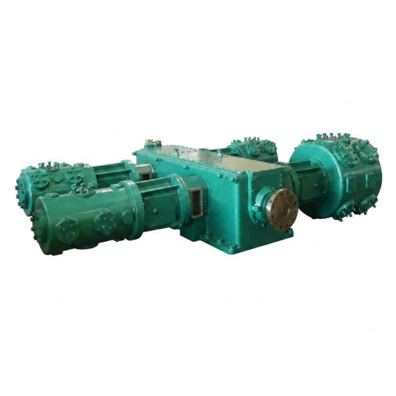
The captured CO₂ — typically delivered from the capture system at 0.1 to 0.3 MPa — must be compressed to pipeline transport pressure (typically 8 to 15 MPa for dense-phase pipeline transport) or directly to wellhead injection pressure (15 to 32 MPa). This is the role of the CO₂ compression train, which consists of one or more reciprocating or centrifugal compressors arranged in series, with interstage cooling, liquid separation, and dehydration between stages. For large CCS projects handling more than 1 million tonnes of CO₂ per year, centrifugal compressors are often used for the lower-pressure stages; for smaller projects, or for the high-pressure injection stages above 10 MPa where centrifugal compressors become impractical, reciprocating compressors are the preferred technology.
Stage 3 — Transport
Compressed CO₂ is transported from the capture facility to the storage site via pipeline in dense-phase or supercritical condition. Dense-phase CO₂ at pressures above 7.38 MPa and temperatures below the critical point behaves as a highly compressed fluid with liquid-like density, enabling efficient long-distance pipeline transport. Booster compression stations may be required along the pipeline route to overcome pressure losses, particularly in hilly or mountainous terrain.
Stage 4 — Injection and Storage
At the storage site, the CO₂ is injected into deep saline aquifers, depleted oil and gas reservoirs, or unmineable coal seams at depths of 800 metres or more, where it is permanently trapped by structural, stratigraphic, residual, dissolution, and mineral trapping mechanisms. Injection pressures at the wellhead typically range from 15 to 32 MPa. In CCUS applications where CO₂ is used for enhanced oil recovery before permanent storage, the compression system may serve dual purposes, with the initial injection phase focused on oil recovery and the final phase transitioning to permanent storage.
A large coal-fired power plant of 1,000 MW capacity generates approximately 7 to 8 million tonnes of CO₂ per year. Capturing 90% of this CO₂ and compressing it to injection pressure requires a compression power of approximately 80 to 120 MW — roughly 8 to 12% of the plant’s gross output. The reciprocating CO₂ injection compressors at the storage wellhead, handling the final injection stage from 10 MPa to 25 MPa, may each require drives of 1,000 to 5,000 kW.
Engineering Challenges Specific to CCS Compression
CCS compression differs from standard industrial gas compression in several respects that have direct consequences for equipment specification and design.
Impurity Composition from Post-Combustion Capture
CO₂ captured by post-combustion amine absorption from power plant or cement kiln flue gas is typically 99 to 99.9% pure, but contains residual impurities that must be accounted for in compressor design. Nitrogen, oxygen, argon, and water vapour are the most common; hydrogen sulphide and sulphur dioxide may be present if the upstream flue gas treatment is incomplete. The presence of oxygen in CO₂ at concentrations above about 100 ppm creates a materials compatibility issue with conventional lubricating oils, and may require special non-hydrocarbon lubricants or oil-free cylinder design. Water vapour above the saturation limit causes corrosion; dehydration to a dew point of −20°C or lower is mandatory before the gas enters the compression train.
Continuous High-Pressure Operation Over Decades
A geological CO₂ storage project typically has an injection phase lasting 20 to 40 years. During this period, the injection compressors must operate with minimal unplanned downtime — the storage permit, the CO₂ supply agreement, and the economic model of the project all depend on reliable continuous injection. This imposes a higher standard of mechanical design and material quality than is typical for shorter-lifecycle industrial applications. Piston rods, valve elements, packing rings, and bearings must be specified with extended service life requirements, and the maintenance philosophy must be based on condition-monitoring data rather than fixed time intervals.
Variable Injection Rate Requirements
The CO₂ injection rate at a CCS well varies over time as reservoir pressure increases, as CO₂ supply from the capture plant fluctuates with industrial output, and as regulatory requirements for monitoring and verification impose periodic injection interruptions. The compressor must therefore be capable of operating efficiently across a wide range of flow rates — typically 50 to 100% of design capacity — without exceeding mechanical limits or compromising reliability. Variable frequency drives on the main motor, combined with suction valve unloaders and clearance pocket volume adjustment, are the standard tools for achieving the required turndown in reciprocating compressor applications.
CO₂ Phase Behaviour and Critical Point Management
CO₂ has a critical point at 31.1°C and 7.38 MPa. In a multi-stage compression train going from near-atmospheric to 25 MPa or above, the gas inevitably passes through or near this critical region during intermediate stages. Near the critical point, CO₂ compressibility and density change rapidly with small variations in temperature and pressure, making thermodynamic modelling with ideal-gas equations unreliable. Real-gas equations of state — Peng-Robinson or GERG-2008 — must be used for all stage-by-stage performance calculations. Interstage cooling and knockout vessels must be designed with conservative margins to prevent any liquid CO₂ from entering a compression cylinder, which would cause hydraulic shock and cylinder failure.
Compressor Selection for Different CCS Capture Technologies
The capture technology used upstream of the compression train has a significant effect on the gas composition and conditions that the compressor must handle. The following table summarises the principal differences.
| Capture Technology | CO₂ Purity | Key Impurities | Inlet Pressure | Compressor Notes |
|---|---|---|---|---|
| Post-combustion (amine) | 99–99.9% | N₂, O₂, H₂O, traces SOx/NOx | 0.1–0.3 MPa | O₂ content may require special lube; dehydration essential |
| Pre-combustion (Selexol/Rectisol) | 95–99.5% | H₂, CH₂, H₂S, COS | 0.5–3 MPa | H₂S requires NACE materials; H₂ affects compression ratio |
| Oxyfuel combustion | 80–98% | N₂, Ar, O₂, SO₂, NOx | 0.1–0.2 MPa | SO₂/NOx react to form acids; corrosion-resistant materials required |
| Direct Air Capture (DAC) | 99.9%+ | H₂O only (post-dehydration) | 0.1–0.15 MPa | High-purity gas; straightforward materials; very low inlet pressure requires large first-stage cylinder |
| Industrial point source (natural CO₂) | 95–99.9% | H₂S, CH₂, N₂ (varies by source) | 0.1–5 MPa | Wide variation; gas analysis critical before specification |
Specification Requirements for CCS CO₂ Injection Compressors
Based on the technical challenges described above, the following specification requirements should be applied to reciprocating CO₂ compressors procured for CCS and CCUS injection service.
API 618 Chapter 3 Study — Mandatory
For CCS injection compressors operating above 10 MPa on a critical injection path, a full API 618 Chapter 3 pulsation and mechanical study is mandatory. The study must model the complete piping system from the compressor suction to the wellhead injection manifold, covering all anticipated operating conditions including minimum and maximum flow rates, variable suction pressure as the CO₂ supply fluctuates, and the effect of parallel compressor operation if multiple units are installed. The study results must demonstrate compliance with API 618 pulsation and vibration limits at all operating conditions before the compressor design is finalised.
Materials for Wet CO₂ and Impurity Tolerance
All wetted pressure parts must be specified in materials compatible with the full range of anticipated gas compositions, including upset conditions. As a minimum, stainless steel should be used for all cylinder liners, heads, interstage piping, separator internals, and valve bodies where any possibility of wet CO₂ exists. For streams containing H₂S above the NACE threshold of 0.0003 MPa partial pressure, NACE MR0175 / ISO 15156 compliant materials and hardness limits must be applied throughout. The materials specification must cover the complete inlet gas composition range, not just the design case.
Distance Piece and Seal Gas System
For CCS injection service, a Type C or Type D distance piece as defined in API 618 is standard, providing two separate compartments between the crankcase and the compression cylinder. The inner compartment is typically purged with dry nitrogen or instrument air to prevent CO₂ from migrating into the crankcase lubricating oil. The outer compartment is vented to a safe location. This arrangement protects the lubrication oil from CO₂ contamination — which would cause foaming and loss of lubrication performance — and prevents crankcase gases from contaminating the CO₂ product stream.
Condition Monitoring and Predictive Maintenance
Given the long operational life required from a CCS injection compressor, comprehensive condition monitoring is not optional — it is a fundamental part of the reliability strategy. The compressor package should be equipped with continuous monitoring of: rod drop (to detect piston ring and packing wear before failure), frame vibration (to detect rod bearing and main bearing degradation), cylinder valve temperature (to detect leaking valves), discharge gas temperature per stage (to detect loss of cooling effectiveness), and lube oil pressure, temperature, and differential pressure across filters. All monitoring data should be recorded by the compressor control system and made available for trending and alarm analysis.
CCS vs CCUS: How Compression Requirements Differ
While CCS and CCUS projects share the same compression technology, there are important differences in how the compressor is operated and what flexibility it must provide.
In a pure CCS project — where the objective is permanent geological storage — the injection rate is typically maintained as close to design capacity as possible to maximise the utilisation of the storage permit and minimise the unit cost of CO₂ stored. The compressor operates predominantly at or near its design point, and turndown is less critical. The primary design priorities are maximum mechanical reliability and minimum energy consumption per tonne of CO₂ injected.
In a CCUS project where CO₂ is used for enhanced oil recovery, the injection profile is more variable. During the EOR phase, injection rates may be adjusted in response to reservoir performance, CO₂ breakthrough at producing wells, and oil price economics. The compressor must therefore provide reliable operation across a wider turndown range, and the control system must be capable of rapid response to changes in injection demand. As the project transitions from the EOR phase to the permanent storage phase, the injection pressure requirements may also change as reservoir pressure increases.
For the low-pressure stages (0.1 to 5 MPa) of a large CCS compression train, centrifugal compressors are often more economical due to their high flow capacity and low maintenance requirements. However, above 10 MPa — and particularly for the final injection stages at 15 to 32 MPa — reciprocating piston compressors are the only practical technology. Centrifugal compressors cannot economically achieve the very high compression ratios required for the final injection stages, and their efficiency falls sharply at the low volumetric flow rates characteristic of the high-pressure end of a CO₂ compression train. For smaller CCS projects handling less than 100,000 tonnes of CO₂ per year, reciprocating compressors are often used for all stages.
Summary: CCS CO₂ Injection Compressor Specification Checklist
Frequently Asked Questions — CO₂ Compressors for CCS and CCUS
Discuss Your CCS Compression Requirements
Our engineering team has extensive experience specifying and manufacturing reciprocating CO₂ compressors for carbon capture and storage applications to API 618 requirements. Provide your process data and we will recommend the right compression solution for your project.