
Overview: Selecting a CO₂ Compressor for Chemical and Petrochemical Plants
Carbon dioxide plays a far wider role in the chemical and petrochemical industry than most outside observers appreciate. It is a reactant in urea synthesis, a working fluid in supercritical extraction, a refrigerant in low-temperature process cooling, a blanketing agent for reactive intermediate storage, a raw material for methanol and formic acid production, and a by-product that must be captured, compressed, and either recycled or safely disposed of in dozens of industrial processes. In every one of these applications, a reciprocating CO₂ compressor is the piece of equipment that makes the process work.
Selecting the right CO₂ compressor for a chemical or petrochemical plant is significantly more complex than for commodity gas compression. The gas stream is rarely pure CO₂. Operating conditions range from cryogenic to high-temperature. The plant environment classifies as a hazardous area. Reliability requirements are stringent because the compressor is often on the critical path of the process — if it stops, the entire plant may stop. This guide sets out the seven criteria that determine whether a CO₂ compressor is fit for chemical and petrochemical service, and provides the specification framework needed to procure equipment that will perform reliably throughout the plant operating life.
How CO₂ Is Used in Chemical and Petrochemical Processes
Before specifying a CO₂ compressor, it is worth understanding the diversity of roles carbon dioxide plays across the chemical sector, because each application imposes different requirements on the compression system.
Urea and Fertilizer Production
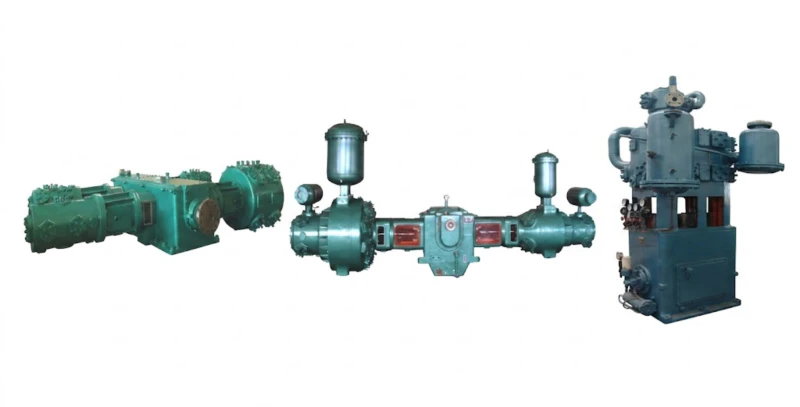
Urea — the world’s most widely used nitrogen fertilizer — is synthesised from ammonia and CO₂ at pressures of 13 to 20 MPa and temperatures around 180°C to 200°C. The CO₂ feed compressor in a urea plant is a critical, continuously operating machine that must deliver a guaranteed flow of high-purity CO₂ at reactor pressure around the clock. Reliability uptime requirements of 98% or above are standard. Reciprocating CO₂ compressors for urea service are typically large M-type or D-type machines with rod loads of 80T to 150T, driven by electric motors of 3,000 kW to 10,000 kW.
Supercritical CO₂ Extraction
Above its critical point of 31.1°C and 7.38 MPa, CO₂ exhibits properties intermediate between a gas and a liquid — it has the dissolving power of a liquid solvent but the transport properties of a gas. Supercritical CO₂ is used as an extraction solvent in the production of specialty chemicals, pharmaceutical intermediates, natural flavourings and fragrances, and caffeine-free coffee and tea. The CO₂ circulation compressor for supercritical extraction duty must operate reliably near the critical point, where gas density and compressibility change rapidly, and must produce a pulse-free, low-vibration flow to avoid disrupting the extraction vessel internals.
CO₂ Recovery and Recycling from Process Off-Gas
Many petrochemical and chemical processes generate CO₂ as a by-product: ammonia reforming, ethylene oxide production, and hydrogen production by steam methane reforming all produce significant CO₂ streams that are either vented, used on-site, or sold as a commodity. Recovery and recompression of this CO₂ requires a compressor that can handle inlet gas at near-atmospheric pressure and raise it to the pressure required for storage, use, or export pipeline delivery — typically 1.5 to 8 MPa. The gas is often contaminated with water, trace hydrocarbons, and other impurities from the process, making materials selection and upstream conditioning particularly important.
Methanol and Synthetic Fuel Production
CO₂ hydrogenation to methanol — using green hydrogen produced by electrolysis — is an emerging pathway for carbon utilisation and Power-to-X applications. CO₂ feed compression to methanol synthesis pressure (5 to 10 MPa) is a key unit operation, with the compressor required to handle a feed stream that may vary in composition as the upstream CO₂ capture system adjusts to varying power availability. Flexibility and reliable turndown are defining requirements for CO₂ compressors in this application.
7 Key Selection Criteria for Chemical Plant CO₂ Compressors
The following seven criteria form the framework for a rigorous CO₂ compressor specification for chemical and petrochemical service. Each criterion reflects a specific engineering reality of the chemical plant environment that distinguishes this duty from more straightforward compression applications.
Chemical plant CO₂ applications span the full pressure range from near-atmospheric recovery to 32 MPa supercritical injection. This is not a single compressor category — low-pressure recovery (0.1 to 2 MPa) uses Z-type or L-type compressors with modest rod loads; medium-pressure applications such as supercritical extraction (6 to 12 MPa) use D-type machines with moderate cylinder sizing; high-pressure applications such as urea synthesis (13 to 20 MPa) require heavy-duty M-type or D-type frames with rod loads of 80T to 150T. The process pressure must be established with certainty before any compressor frame can be selected. A data sheet that specifies the design pressure, operating pressure, and the maximum credible overpressure scenario is the essential starting point.
Chemical process CO₂ streams are rarely pure. CO₂ from ammonia plant reforming may contain residual CH₂, H₂, N₂, and H₂S. Supercritical extraction recycle CO₂ may carry trace amounts of the solute. CO₂ from fermentation contains ethanol and acetaldehyde. Each impurity affects the thermodynamic behaviour of the gas, the compressor performance calculations, and the material requirements for wetted parts. Provide the compressor manufacturer with a complete gas composition table covering the design case, the startup case, and the maximum and minimum anticipated variation ranges. Failure to disclose impurities has been the single most common root cause of premature compressor failures in chemical plant service.
For dry CO₂ at pressures below the critical region, carbon steel cylinders and piping are generally acceptable from a corrosion standpoint. However, any possibility of free water in the gas stream demands stainless steel or duplex stainless steel for all wetted pressure parts, because CO₂ in the presence of water forms carbonic acid that attacks carbon steel at rates of several millimetres per year. For CO₂ streams containing H₂S, additional requirements apply: NACE MR0175 / ISO 15156 compliant materials must be specified for all components in contact with sour gas, and hardness limits on weld heat-affected zones must be strictly controlled. Do not allow materials to be specified for the design-case gas only — specify for the maximum impurity concentration that could plausibly occur during the plant lifetime, including startup, shutdown, and upset conditions.
All chemical and petrochemical plant compressor installations are classified as hazardous areas under IEC 60079 and the ATEX directive. The compressor package — including the drive motor, control panels, junction boxes, instruments, and all electrical equipment — must be rated for the appropriate hazardous area zone. For most CO₂ compressor installations in chemical plants, the hazardous area zone arises from other flammable gases or vapours present in the plant environment rather than from CO₂ itself. Require the compressor manufacturer to confirm the hazardous area classification applicable to the installation and to certify all electrical equipment accordingly. An ATEX certificate covering only one component of the package is not sufficient — every electrical item must be individually certified.
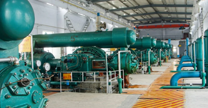
A CO₂ compressor on the critical path of a chemical process — such as the CO₂ feed to a urea reactor — must operate without unplanned shutdown for 8,000 hours or more between maintenance intervals. Achieving this requires a combination of robust mechanical design (conservative rod loads, oversized bearings, extended valve life), comprehensive condition monitoring (vibration, rod drop, temperature), and a planned maintenance philosophy based on operating hours and condition indicators rather than calendar time. For truly critical applications, the plant owner must consider whether a full spare compressor or spare cylinder capability is economically justified. The cost of a spare compressor is often small compared to the revenue loss from a single extended unplanned shutdown.
Pressure pulsations generated by a reciprocating compressor can propagate through connected process piping and cause resonance, instrument errors, valve wear, and structural fatigue in pipework. In a chemical plant environment where the compressor is connected to a complex network of process vessels, heat exchangers, and control valves, pulsation management is essential. API 618 defines three levels of pulsation and mechanical study, from a simplified desktop analysis (Chapter 1) to a full digital simulation and mechanical response analysis (Chapter 3). For chemical plant CO₂ service at pressures above 5 MPa or flows above 30 Nm³/min, a Chapter 3 study should be specified. For lower pressure or flow applications, a Chapter 2 study is generally adequate. Specify the study requirement in the enquiry, not as an afterthought during detailed engineering.
Multi-stage CO₂ compression generates significant heat of compression that must be removed between stages to prevent overheating and to control the approach to the critical point. Chemical plants with access to cooling water typically use water-cooled interstage coolers — more compact, more effective, and lower in capital cost than air-cooled alternatives. However, cooling water quality, availability, and the risk of CO₂ leakage into the cooling water system must be evaluated. Plants in water-scarce locations, or in regions where ambient temperatures make air cooling economical, may prefer air-cooled fin-fan coolers as part of a self-contained skid package. The cooling system design must be integrated with the compressor thermodynamic analysis from the outset, not treated as a separate utility.
Technical Specifications by Chemical Plant Application
The following table summarises typical compressor specifications for the principal CO₂ compression applications in chemical and petrochemical plants. These ranges should be used as a starting point for engineering design; final specifications must be confirmed through a detailed process simulation.
| Application | Inlet Pressure | Discharge Pressure | Flow Range | Frame Recommendation |
|---|---|---|---|---|
| Urea Synthesis (CO₂ feed) | 0.05–0.3 MPa | 13–20 MPa | 50–300 Nm³/min | M-Type, 4–6 stage |
| Supercritical CO₂ Extraction | 1.0–2.0 MPa | 7–30 MPa | 5–80 Nm³/min | D-Type or M-Type |
| CO₂ Recovery / Recompression | Near-atm (0–0.1 MPa) | 1.5–8 MPa | 10–200 Nm³/min | D-Type or L-Type |
| Methanol Synthesis (CO₂ feed) | 0.1–1.0 MPa | 5–10 MPa | 10–150 Nm³/min | D-Type, 3–4 stage |
| Inert Gas Blanketing / Padding | Ambient | 0.5–2 MPa | 1–20 Nm³/min | Z-Type or L-Type |
| CO₂ as Refrigerant (Transcritical) | 3–5 MPa | 8–14 MPa | 5–60 Nm³/min | D-Type, oil-lubricated |
Managing CO₂ Phase Behaviour Across the Pressure Range
The thermodynamic behaviour of CO₂ introduces engineering challenges that are not present in air or nitrogen compression, and that vary significantly depending on where in the pressure range the compressor operates.
At low inlet pressures (below 5 MPa) and moderate temperatures, CO₂ behaves essentially as an ideal gas and can be handled with conventional compressor designs. As the discharge pressure approaches the critical pressure of 7.38 MPa, the gas compressibility factor deviates significantly from unity, and standard ideal-gas thermodynamic calculations become unreliable. Compressor performance calculations for all stages that operate in the range of 5 MPa to 12 MPa must use real-gas equations of state — the Peng-Robinson or Benedict-Webb-Rubin equations are most commonly used for CO₂ — to obtain accurate predictions of discharge temperature, power consumption, and volumetric efficiency.
Above the critical pressure — in the supercritical region — CO₂ is a single-phase fluid and the liquid carry-over risk disappears. However, the very high density of supercritical CO₂ means that volumetric flow rates at the high-pressure stage inlet are very low. This requires careful cylinder sizing to avoid excessively small valve dimensions that would compromise valve life and efficiency. For urea synthesis compressors operating at 15 to 20 MPa, the final stage cylinder bore may be as small as 80 to 150 mm, requiring precision machining and high-quality forged steel cylinder construction.
Oil-Free vs Oil-Lubricated Cylinders: Making the Right Choice
One of the most consequential decisions in specifying a chemical plant CO₂ compressor is whether the compression cylinders should be oil-lubricated or oil-free (non-lubricated). This choice affects gas purity, maintenance intervals, cylinder design, and operating cost throughout the equipment life.
When Oil-Free Cylinders Are Required
Oil-free compression is mandatory wherever hydrocarbon contamination of the CO₂ product would compromise product quality, damage downstream catalysts, or violate process specifications. Applications requiring oil-free cylinders include: supercritical CO₂ extraction for food or pharmaceutical products; CO₂ feed to catalytic reactors where oil can poison the catalyst; CO₂ for beverage carbonation; and high-purity CO₂ for electronics or semiconductor manufacturing. Oil-free cylinders use self-lubricating PTFE or PEEK piston rings and packing seals, with a double-compartment distance piece isolating the crankcase lubrication system from the compression circuit.
When Oil-Lubricated Cylinders Are Acceptable
For chemical plant applications where trace oil contamination in the CO₂ does not affect the process — such as CO₂ feed to a urea reactor, CO₂ for pipeline injection, or CO₂ recompression for geological storage — oil-lubricated cylinders are generally preferred. Oil lubrication allows the use of smaller cylinder bores with closer wall tolerances, extends piston ring and packing life compared to oil-free designs, and generally permits higher operating speeds. The specific oil injection rate and oil type must be selected carefully for compatibility with the CO₂ gas and the downstream process.
Choose oil-free when: the CO₂ contacts food, pharmaceutical products, or sensitive catalysts; downstream process specifications set an oil content limit below 1 ppm; or the plant operator has a corporate policy of oil-free compression for all process gas services.
Choose oil-lubricated when: the downstream process is tolerant of trace hydrocarbons; the discharge pressure exceeds 15 MPa (where oil-free ring wear rates increase significantly); or maximum piston ring and packing service life is a critical reliability requirement.
Summary: Chemical Plant CO₂ Compressor Specification Checklist
Frequently Asked Questions — CO₂ Compressors for Chemical and Petrochemical Plants
Discuss Your Chemical Plant CO₂ Compression Requirements
Our engineering team has extensive experience specifying and manufacturing reciprocating CO₂ compressors for chemical and petrochemical process applications to API 618 requirements. Send us your process data sheet and we will provide a detailed technical recommendation.