
Overview: High-Purity CO₂ Compression in Semiconductor and Electronics Manufacturing
The semiconductor fabrication process is among the most contamination-sensitive manufacturing environments in existence. A single sub-micron particle or a trace concentration of a chemical contaminant deposited on a silicon wafer during processing can ruin an entire chip die — and at the scale of modern fabs producing thousands of wafers per day, even a contamination event affecting a fraction of one percent of production represents a significant financial loss. For this reason, every gas, chemical, and material introduced into the cleanroom environment must meet extraordinarily rigorous purity specifications, verified by analytical methods capable of detecting contamination at the parts-per-billion or even parts-per-trillion level.
Carbon dioxide is used in several semiconductor manufacturing processes: supercritical CO₂ cleaning of photoresist residues, CO₂ as a carrier gas in chemical vapour deposition (CVD) processes, CO₂ for wafer surface conditioning, and liquid CO₂ as a cryogenic cleaning medium for particle removal. In every one of these applications, the CO₂ must meet electronics-grade purity specifications — typically 99.999% (5N) or above, with hydrocarbon contamination below 1 part per billion and no detectable oil. The high-purity CO₂ compressor that delivers and recirculates CO₂ within these systems must be designed to a fundamentally different standard from industrial process gas compressors: it must not contaminate the gas it handles, must be constructed with cleanroom-compatible materials and surface finishes, and must operate reliably in close proximity to sensitive semiconductor process equipment. This guide covers the applications, technical requirements, and specification framework for CO₂ compressors in electronics and semiconductor manufacturing.
How CO₂ Is Used in Semiconductor Manufacturing
The applications of CO₂ in semiconductor and electronics manufacturing span several distinct unit operations, each with specific requirements that influence the compression system design.
Supercritical CO₂ Cleaning (scCO₂)
Supercritical CO₂ — CO₂ maintained above its critical point of 31.1°C and 7.38 MPa — exhibits liquid-like dissolving power combined with gas-like transport properties, making it an exceptionally effective solvent for removing photoresist, polymer residues, and sub-micron particles from wafer surfaces. Unlike wet chemical cleaning processes, scCO₂ leaves no liquid residue (since it is released as gas upon depressurisation), cannot collapse narrow high-aspect-ratio structures through surface tension forces, and can penetrate deep trenches and vias that liquid solvents cannot reach effectively. Supercritical CO₂ cleaning systems operate at 7.4 to 30 MPa and 31 to 80°C. The CO₂ is circulated through the cleaning vessel by a dedicated high-pressure CO₂ pump or compressor, which must introduce zero contaminants into the CO₂ stream throughout the cleaning process.
CO₂ as Process Gas in CVD and Etching
CO₂ is used as a carrier or reactive gas in several chemical vapour deposition and plasma etching processes. In atomic layer deposition (ALD) and related processes, CO₂ serves as an oxidant or carrier gas at pressures of 0.01 to 0.1 MPa. In plasma-assisted etching, CO₂ is sometimes added to the etch gas mixture to control selectivity. In these applications, the CO₂ purity requirement is driven by the sensitivity of the process to trace metal contamination — even sub-ppb concentrations of sodium, potassium, iron, or heavy metals can shift device threshold voltages, degrade gate oxide integrity, or alter contact resistance. The CO₂ used in these processes must therefore be certified to trace metal specifications as well as gas purity, and all components in the gas handling and compression system that contact the CO₂ must be free of leachable metals.
Liquid CO₂ Cryogenic Particle Cleaning
Liquid CO₂ sprayed through a nozzle at controlled pressure and temperature produces a mixture of CO₂ gas and dry ice particles (snow) that can physically remove sub-micron particles from wafer surfaces without chemical attack or residue. This technique — known as CO₂ snow cleaning or carbon dioxide cryogenic cleaning — is used for particle removal from reticles, optical surfaces, and wafer surfaces where wet cleaning is undesirable. The CO₂ must be exceptionally pure and completely oil-free: even nanogram quantities of oil in the CO₂ stream would be deposited on the cleaned surface, causing device failures in subsequent process steps.
CO₂ Atmosphere Control in Wafer Storage and Transfer
Certain wafer storage and transfer environments use CO₂ as a controlled atmosphere to suppress the formation of native oxide on silicon surfaces or to maintain specific humidity conditions in storage environments for hygroscopic materials. In these applications, the CO₂ quality requirements are less extreme than in direct-contact cleaning processes, but the purity standard still far exceeds that of industrial or food-grade CO₂.
Purity Standards for Electronics-Grade CO₂
Electronics-grade CO₂ is produced and certified to purity specifications that are orders of magnitude more stringent than food-grade or industrial-grade CO₂. The following table illustrates the progression of purity requirements across application grades.
| Parameter | Industrial Grade | Food Grade (ISBT) | Electronics Grade (5N) |
|---|---|---|---|
| CO₂ Purity | ≥ 99.0% | ≥ 99.9% | ≥ 99.999% (5N) |
| Total Hydrocarbons | ≤ 10 ppm | ≤ 20 ppm | ≤ 1 ppb |
| Total Oil Content | ≤ 5 ppm | ≤ 0.1 ppm | Not detectable (<0.01 ppb) |
| Moisture (H₂O) | ≤ 200 ppm | ≤ 20 ppm | ≤ 0.5 ppm (−65°C dew point) |
| Particle Count | Not controlled | Not typically controlled | ≤ 1 particle/cm³ at ≥ 0.1 µm |
| Trace Metals (each) | Not typically controlled | Not typically controlled | ≤ 0.1 ppb each (Na, K, Fe, etc.) |
These specifications illustrate why a conventional industrial or even food-grade CO₂ compressor is completely unsuitable for semiconductor applications. The gap between food-grade total hydrocarbon limits (20 ppm) and electronics-grade limits (1 ppb) is a factor of 20,000. No amount of downstream filtration can compensate for a compressor that introduces oil or hydrocarbon contamination into the gas stream at parts-per-million concentrations; only a compressor designed from the outset to introduce zero contamination can meet these specifications.
Engineering Requirements for High-Purity CO₂ Compressors
A CO₂ compressor for semiconductor and electronics manufacturing must satisfy requirements that go beyond the oil-free cylinder specification applied in food-grade applications. Every aspect of the compressor’s materials, surface finish, sealing, and construction must be evaluated for its potential to introduce contamination into the gas stream.
Oil-Free Compression: The Absolute Baseline
Oil-free cylinder design — with PTFE or PEEK self-lubricating piston rings and packing seals, and a double-compartment distance piece isolating the crankcase from the compression circuit — is the minimum requirement and the essential starting point. However, in semiconductor applications the PTFE or PEEK ring material itself must be evaluated for purity: standard commercial-grade PTFE contains fillers and processing additives that can outgas trace hydrocarbons. For the most critical semiconductor applications, ultra-high-purity PTFE or PEEK with documented outgassing specifications should be specified, and the piston ring and packing materials should be pre-baked at elevated temperature in a clean environment before installation to remove adsorbed hydrocarbons and moisture.
Surface Finish: Electropolished Stainless Steel Throughout
All internal surfaces of the compression cylinder, valves, discharge piping, and any component that contacts the CO₂ gas stream must be made from high-purity austenitic stainless steel (316L or better) with an electropolished (EP) interior surface finish. Electropolishing removes the rough surface asperities of mechanically finished stainless steel, producing a smooth, chromium-oxide-rich passive layer that resists adsorption of trace hydrocarbons and outgassing of metal ions. The electropolish specification should define both the surface roughness (Ra ≤ 0.25 µm interior, typically) and the requirement for a passive layer verified by electrochemical testing per SEMI F19 or equivalent. Bead-blasted or mechanically polished interior surfaces are not acceptable for 5N semiconductor applications.
Seal Material Selection and Outgassing Control
Every elastomeric and polymeric seal in the compression circuit must be selected for compatibility with high-purity CO₂ and for low outgassing. Standard nitrile (NBR) or neoprene O-rings are incompatible with CO₂ — CO₂ permeates these materials rapidly, causing swelling and accelerated extraction of plasticisers and vulcanisation compounds into the gas stream. For high-purity CO₂ service, perfluoroelastomer (FFKM) seals — such as Kalrez or equivalent — are specified. FFKM materials have excellent resistance to CO₂ permeation and extremely low outgassing rates. All seals should be certified to semiconductor-grade outgassing specifications and supplied with full material traceability documentation.
Moisture Control: Deep Dehydration
Electronics-grade CO₂ specifications typically require a moisture content of 0.5 ppm or below — corresponding to a dew point of approximately −65°C. This level of dehydration cannot be achieved by conventional molecular sieve dryers alone in most applications. For the most stringent semiconductor requirements, a two-stage drying train — molecular sieve followed by a getter-type purifier — is required. The compressor package must include a high-efficiency suction gas dryer system, and all internal surfaces must be thoroughly cleaned and passivated before the compressor is placed in service to minimise moisture outgassing from internal surfaces during initial operation.
Particle Control: Zero-Particle Valves and Clean Assembly
Particles generated within the compressor — from piston ring wear, valve seat wear, or debris from construction — would contaminate the CO₂ and ultimately deposit on wafer surfaces in the process tool. Particle control requires: specification of gas valves designed for low particle generation (spring-loaded poppet or diaphragm valves rather than plate valves); assembly of all gas-wetted components in a cleanroom environment (ISO Class 7 or better); helium leak testing of all assembled joints and fittings before the compressor leaves the factory; passivation and purging of the complete compression circuit with ultra-high-purity nitrogen before the compressor is shipped; and installation of a point-of-use submicron particle filter at the compressor outlet as the final contamination barrier.
Pressure, Flow, and System Design for Semiconductor CO₂ Applications
The pressure and flow requirements for CO₂ compressors in semiconductor applications vary considerably by process type.
| Application | Pressure Range | Flow Range | Purity Level |
|---|---|---|---|
| Supercritical CO₂ cleaning (scCO₂) | 7.4–30 MPa | 0.5–10 Nm³/min | 5N minimum; 6N preferred |
| CVD carrier gas supply | 0.2–1.0 MPa | 0.1–5 Nm³/min | 5N; trace metal ≤ 0.1 ppb |
| CO₂ snow cleaning | 5–8 MPa | 0.1–2 Nm³/min | 5N; particles ≤ 1/cm³ |
| Wafer atmosphere control | 0.1–0.5 MPa | 0.05–1 Nm³/min | 4N to 5N |
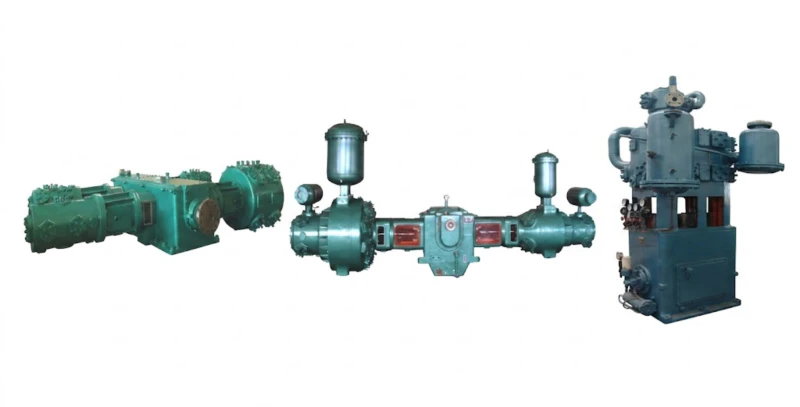
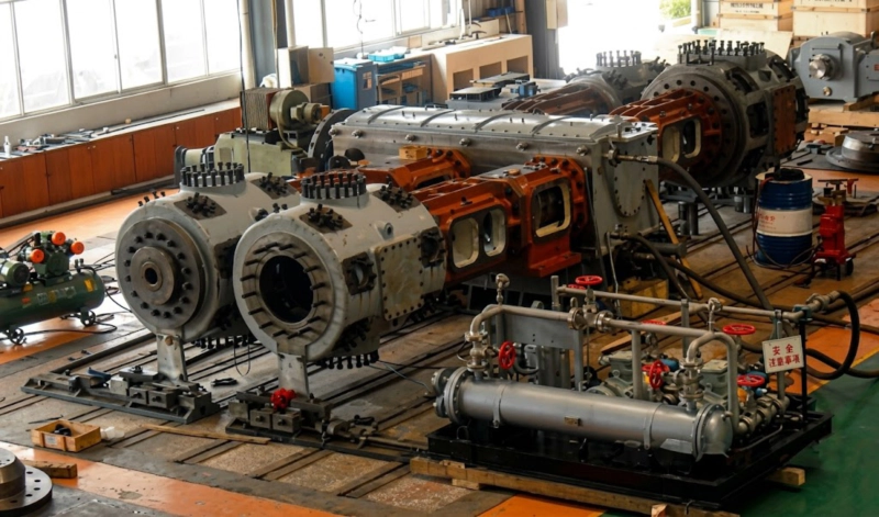
The relatively small flow rates required in most semiconductor CO₂ applications — typically 0.1 to 10 Nm³/min — mean that Z-type vertical reciprocating compressors or single-stage diaphragm compressors are the most commonly used configurations. Z-type reciprocating compressors offer the advantages of oil-free operation, straightforward cleanroom-compatible construction, and the ability to operate across the full pressure range from low-pressure CVD supply to supercritical cleaning applications. Diaphragm compressors — which use a flexible metal membrane rather than a piston to compress the gas — provide an additional level of hermetic isolation between the drive mechanism and the gas circuit, and are used for the most extreme purity requirements where even the trace outgassing of PTFE piston rings is not acceptable.
Traceability, Documentation, and Qualification Requirements
Semiconductor manufacturers impose documentation and traceability requirements on process equipment that go significantly beyond the material test certificates and quality management certifications required in other industries. For a CO₂ compressor destined for a semiconductor facility, the following documentation is typically required as part of the equipment qualification process.
Summary: High-Purity CO₂ Compressor Specification Checklist for Semiconductor Applications
Frequently Asked Questions — High-Purity CO₂ Compressors for Semiconductor Manufacturing
Discuss Your Semiconductor CO₂ Compression Requirements
Our engineering team has experience designing oil-free CO₂ compressors for high-purity and electronics-grade applications. Provide your process purity specification, pressure, and flow requirements and we will recommend the right configuration for your facility.