
Overview: CO₂ Injection Compressors for Enhanced Oil Recovery
Enhanced oil recovery — commonly abbreviated as EOR — is the third and final phase of oil field production. After primary recovery driven by natural reservoir pressure and secondary recovery through water flooding, EOR techniques are deployed to extract the remaining crude that conventional methods cannot reach. CO₂ flooding, also known as CO₂ injection or miscible flooding, is one of the most effective and widely used EOR methods in the world, capable of recovering an additional 7 to 23 percent of original oil in place from mature fields.
At the heart of every CO₂ EOR project is the CO₂ injection compressor — the machine responsible for taking carbon dioxide gas at pipeline or source pressure and raising it to the supercritical injection pressure required to drive CO₂ deep into the reservoir. Selecting the wrong compressor for this duty has direct consequences for project economics, injection reliability, and ultimate oil recovery. This guide provides the engineering and procurement information needed to specify a CO₂ injection compressor correctly for EOR service.
How CO₂ Flooding Works in Enhanced Oil Recovery
CO₂ EOR works on the principle of miscibility — the ability of CO₂ to mix with crude oil under sufficient pressure, reducing the oil’s viscosity and surface tension and allowing it to flow toward the producing wells. When injected above the minimum miscibility pressure (MMP), CO₂ swells the oil, strips light hydrocarbons from the crude, and generates a miscible front that sweeps oil toward the production well.
The minimum miscibility pressure for most crude oil and CO₂ systems ranges from 7 MPa to 20 MPa depending on reservoir temperature and oil composition. However, actual injection pressures at surface are considerably higher — typically 15 MPa to 32 MPa — to account for hydrostatic head losses in the injection wellbore and to maintain a sufficient pressure differential across the reservoir. This is why high-pressure, large-capacity reciprocating compressors are the preferred technology for CO₂ EOR injection duty.
CO₂ used in EOR projects is sourced from three main pathways: natural CO₂ reservoirs (as found in the Permian Basin), industrial point sources such as power plants, fertilizer plants, and cement facilities, and — increasingly — carbon capture systems designed specifically to provide injection-ready CO₂ from industrial flue gas. In all three cases, the CO₂ arrives at the injection facility at a pressure and composition that requires recompression and conditioning before it can be injected into the reservoir.
A well-designed CO₂ miscible flood can recover between 7% and 23% of original oil in place (OOIP) that primary and secondary recovery methods have left behind. At current oil prices, even a modest 5% improvement in recovery from a mature field of 100 million barrels represents a significant economic return on compressor capital investment.
Technical Challenges of CO₂ Injection Compression
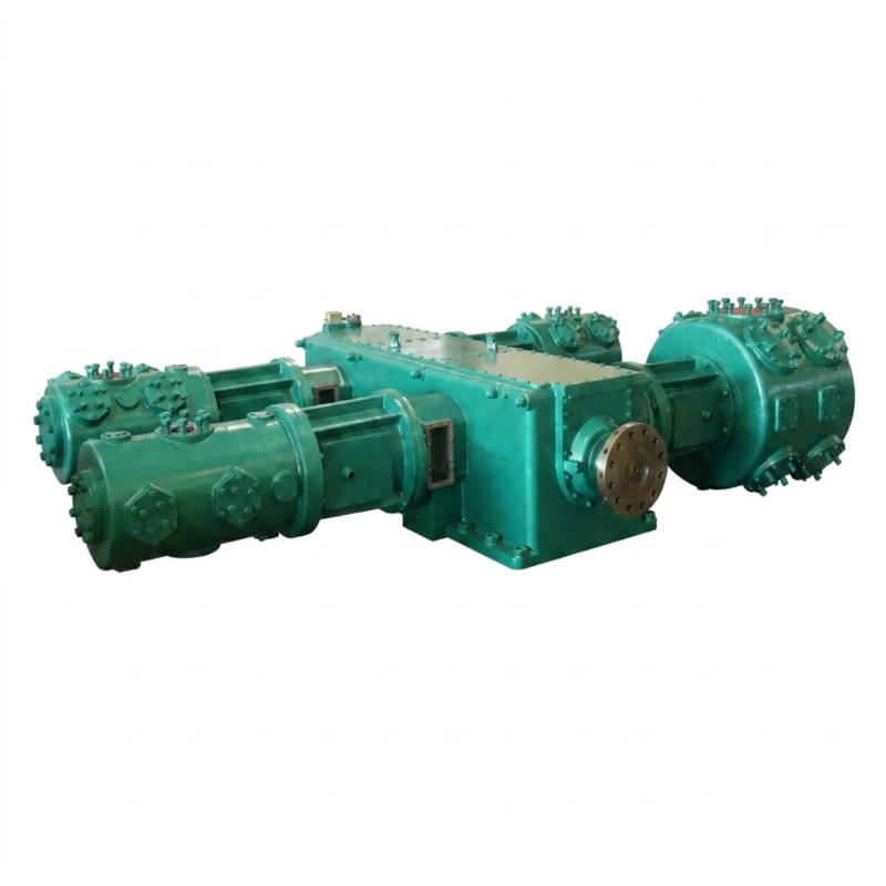
Compressing CO₂ for EOR injection presents a set of engineering challenges that are distinct from those encountered in standard process gas or air compression. Understanding these challenges is essential to specifying equipment that will perform reliably for the 15–25 year life of a typical EOR project.
Phase Behaviour and Condensation Risk
CO₂ has a critical point at 31.1°C and 7.38 MPa. In a multi-stage compression system, the gas passes through or near the critical region during intermediate stages, where CO₂ can transition between gaseous and liquid phases with relatively small changes in temperature or pressure. Liquid CO₂ carry-over into a compressor cylinder causes hydraulic shock — a potentially catastrophic event for rods, pistons, and cylinders. Compressor design for EOR must therefore include carefully engineered stage pressures, interstage cooling control, and high-efficiency liquid knock-out vessels at each interstage separator.
Corrosion in the Presence of Water
Dry CO₂ is relatively non-corrosive to carbon steel. However, if free water is present — whether in the inlet gas stream or as condensate formed during compression — CO₂ dissolves into the water to form carbonic acid (H₂CO₃), which aggressively attacks carbon steel at rates of several millimetres per year. For CO₂ injection compressors, this means all wetted surfaces in contact with potentially wet CO₂ must be specified in corrosion-resistant materials: stainless steel cylinders, duplex or super-duplex interstage piping, and corrosion-resistant valve materials. Upstream dehydration to a dew point of −20°C or lower is the most important upstream protection measure.
High Discharge Pressure and Rod Load
Discharge pressures of 20–32 MPa place extreme mechanical demands on the compressor. Rod loads — the axial forces acting on the piston rod during compression — scale directly with pressure differential and piston area. EOR compressors must be designed with sufficient frame stiffness and rod load capacity to withstand these forces continuously without fatigue failure. API 618 specifies maximum allowable combined rod loads for reciprocating compressors; EOR applications typically require heavy-duty frames with rod load ratings of 50T to 150T.
Pulsation and Vibration Management
Reciprocating compressors inherently generate pressure pulsations in the piping system. In CO₂ EOR service — where the compressor is connected to long injection pipelines and wellhead systems — uncontrolled pulsations can cause resonance in the piping, accelerated valve wear, instrument measurement errors, and structural fatigue of piping supports. API 618 Chapter 3 requires a detailed pulsation and mechanical study for all process reciprocating compressors, including acoustic simulation and mechanical response analysis. EOR project specifications should always include a full Chapter 3 study.
API 618 Compliance for CO₂ EOR Injection Compressors
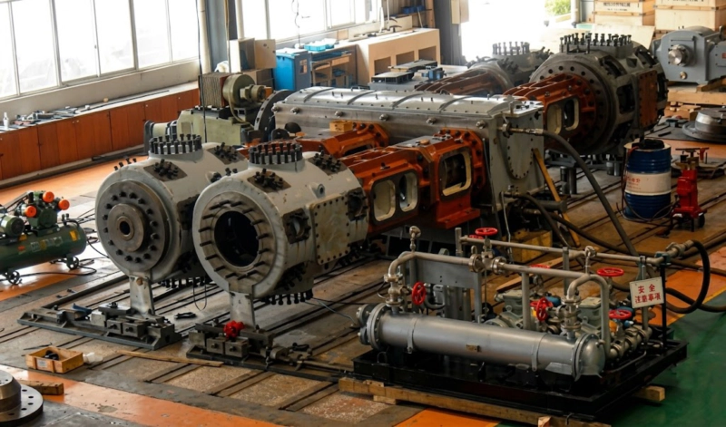
API Standard 618 — Reciprocating Compressors for Petroleum, Chemical, and Gas Industry Services — is the benchmark specification applied to virtually all CO₂ injection compressors used in EOR projects by major oil and gas operators worldwide. Published by the American Petroleum Institute and now in its fifth edition, API 618 defines requirements covering mechanical design, materials, fabrication, inspection, testing, and documentation for reciprocating process compressors.
For CO₂ EOR injection service, the most relevant provisions of API 618 include:
Compressor Frame Selection for CO₂ EOR Service
The choice of compressor frame configuration for CO₂ EOR injection is driven by three primary factors: the required flow and pressure combination, the installation environment (onshore well pad, offshore platform, or central injection station), and the need for dynamic balance to minimise foundation loads and vibration in the piping system.
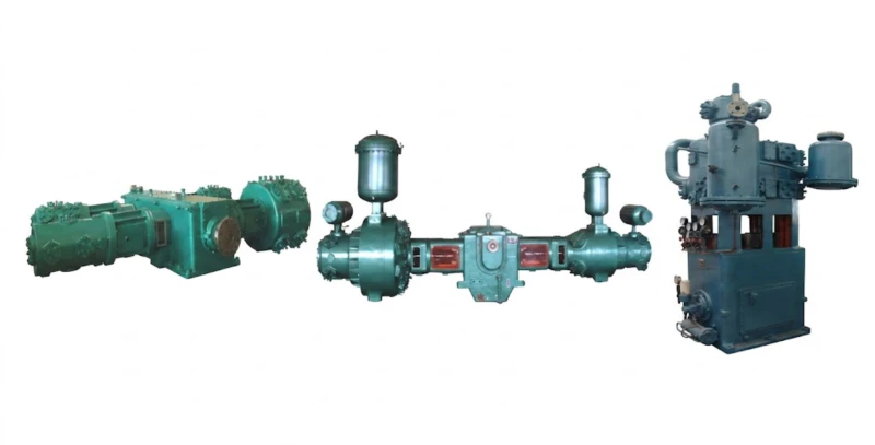
M-Type Opposed Balance — Preferred for Large EOR Projects
For large-scale CO₂ EOR injection stations handling flows of 50 Nm³/min and above at pressures up to 32 MPa, the M-type opposed-balance horizontal compressor is the most widely specified configuration. In the M-type design, cylinders are arranged horizontally on both sides of the crankshaft in an opposed configuration, with each crank throw paired with a counterpart 180° away. This arrangement results in near-perfect cancellation of primary inertia forces, minimising the unbalanced forces transmitted to the foundation and the connected piping system.
The practical benefits for EOR installations are significant: M-type machines can be installed on simple grout-levelled concrete pads without the heavy, reinforced foundations required by less balanced configurations. The low vibration characteristic also reduces fatigue loading on the high-pressure injection piping — a critical consideration for 20–25 year project design life.
D-Type Horizontal — Medium-Scale EOR Applications
For medium-scale EOR injection applications in the range of 20 to 80 Nm³/min, the D-type horizontal compressor offers a practical balance of capacity, mechanical simplicity, and cost. D-type machines are available in two-, four-, and six-cylinder configurations and can be engineered for discharge pressures up to 32 MPa. While not achieving the full dynamic balance of the opposed M-type, D-type machines are well-proven in CO₂ service and widely available in skid-mounted packages suitable for remote well pad installation.
| Frame Type | Typical Flow Range | Max. Pressure | Balance | Best Fit |
|---|---|---|---|---|
| M-Type (Opposed) | 50 – 400 Nm³/min | Up to 32 MPa | Excellent | Central injection stations, large fields |
| D-Type (Horizontal) | 20 – 150 Nm³/min | Up to 32 MPa | Good | Medium fields, well pad injection |
| L-Type | 10 – 80 Nm³/min | Up to 25 MPa | Moderate | Smaller satellite injection points |
| Z-Type (Vertical) | 2 – 30 Nm³/min | Up to 20 MPa | Fair | Pilot EOR projects, remote single wells |
Staging, Pressure, and Flow: Key Specification Parameters
Defining the correct number of compression stages, interstage pressures, and overall flow rate is the most critical engineering task in specifying a CO₂ EOR injection compressor. The following parameters must be established before equipment selection can proceed.
| Parameter | Typical EOR Range | Design Note |
|---|---|---|
| Inlet Pressure | 0.1 – 5.0 MPa | Determined by CO₂ source (pipeline, capture plant) |
| Discharge Pressure | 15 – 32 MPa | Must exceed MMP plus wellbore hydrostatic losses |
| Number of Stages | 3 – 6 stages | Compression ratio per stage typically limited to 3:1 – 4:1 |
| Flow Capacity | 20 – 400 Nm³/min | Based on reservoir injectivity and CO₂ supply volume |
| Rod Load (Combined) | 50 – 150 T | Per API 618 combined rod load limits |
| Motor Power | 500 – 10,000 kW | Depends on compression ratio and flow rate |
| Inlet Gas Composition | 95–99.9% CO₂ | H₂S, CH₂, N₂ impurities affect MMP and materials |
A practical consideration often overlooked in early project planning is the turndown requirement. CO₂ EOR injection rarely operates at a single fixed rate throughout the project life. As reservoir pressure increases in the swept zone, injectivity changes. As CO₂ supply from capture facilities fluctuates, available volumes vary. The compressor must be capable of efficient operation across a range of flow rates — typically 60% to 100% of design capacity — without compromising reliability or causing surge. Variable speed drives, suction valve unloaders, and clearance pocket systems are the main tools for achieving the required turndown.
Skid-Mounted Package Design for Remote EOR Installations
Most CO₂ EOR injection compressors are delivered as fully factory-assembled, pre-tested skid packages rather than loose equipment. The skid package approach offers decisive advantages for EOR projects, which are often located in remote oil fields far from the nearest maintenance infrastructure.
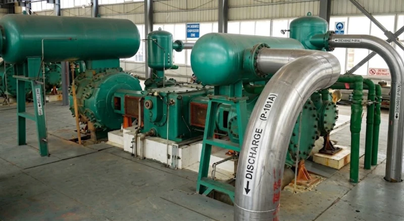
A fully engineered CO₂ EOR injection compressor skid package typically integrates: the main compressor unit (frame, cylinders, valves, piston rods), the drive motor (fixed or variable speed), suction scrubbers and inlet knockout vessels, interstage coolers and separators, high-pressure discharge pulsation dampeners, the lube oil system with reservoir, pump, cooler, and filter, an instrument air or nitrogen purge system for distance pieces, a local control panel with PLC, process sensors, and safety shutdown logic, and all interconnecting high-pressure piping pre-fabricated and tested. Factory pre-assembly and testing of the complete package allows site commissioning to proceed in days rather than weeks.
For offshore EOR applications, the skid design must also account for space and weight constraints, the need for full hazardous area (ATEX) electrical classification, and the additional structural loading from wave-induced motion. Offshore CO₂ injection compressors are typically designed to DNV or equivalent marine standards in addition to API 618, with special attention to corrosion protection in the marine atmosphere.
7 Key Criteria for Specifying a CO₂ EOR Injection Compressor
Obtain a reservoir study confirming the minimum miscibility pressure for your specific crude and CO₂ composition. Add hydrostatic head and pressure losses in the wellbore and surface injection piping to determine the required compressor discharge pressure. Add a 10% design margin.
Obtain a full gas analysis including CO₂ purity, H₂S, CH₂, N₂, H₂O content, and any sulphur compounds. Even small concentrations of H₂S dramatically change material requirements. Specify the complete composition range — not just the design point — as the compressor must handle variations in source gas quality throughout the project life.
Do not accept a Chapter 1 or Chapter 2 study for high-pressure EOR injection service. The Chapter 3 study must model the complete piping system from compressor inlet to wellhead, including the effect of multiple compressors operating in parallel if applicable. Results must demonstrate compliance with API 618 vibration and pulsation limits at all operating conditions.
Require stainless steel or duplex stainless steel for all wetted pressure parts: cylinder liners and heads, interstage piping and cooler tubes, separator internals, and valve bodies. Specify corrosion allowances for all carbon steel structural components. Do not rely on upstream dehydration alone as the sole corrosion barrier — the compressor itself must be tolerant of occasional wet gas excursions.
Specify the minimum and maximum flow rates the compressor must handle reliably. For EOR projects with variable CO₂ supply, a variable frequency drive (VFD) on the main motor combined with suction valve unloaders is the most flexible approach. Ensure the compressor manufacturer confirms stable operation across the full operating envelope without exceeding rod load or valve velocity limits.
Insist on complete skid assembly at the manufacturer’s facility, including all auxiliary systems, instrumentation, and high-pressure piping. The complete package must undergo a witnessed FAT verifying mechanical performance, lube oil system function, safety shutdown logic, and vibration levels. For remote EOR installations, a non-witnessed FAT is not acceptable.
EOR projects have 15–25 year operating lives. Confirm that the compressor manufacturer commits to spare parts supply for the full project life, not just the warranty period. Establish a recommended spare parts list for commissioning, two-year operating stock, and major overhaul, and verify that these parts are held in stock or can be manufactured within contractually agreed lead times.
Summary: CO₂ EOR Injection Compressor Specification Checklist
Frequently Asked Questions — CO₂ EOR Injection Compressors
Ready to Specify Your CO₂ Injection Compressor?
Our engineering team has extensive experience designing reciprocating CO₂ compressors for EOR injection service to API 618 requirements. Provide your process conditions and we will recommend the right configuration for your project.