
Overview: Why CO₂ Removal Is Critical in LNG Plant Operations
The production of liquefied natural gas requires feedstock gas to be cooled to approximately −162°C — the temperature at which methane liquefies at atmospheric pressure. At this extreme temperature, any CO₂ present in the gas stream will solidify (freeze) at concentrations above approximately 50 parts per million by volume, forming solid plugs that block heat exchanger passages, clog process equipment, and cause the liquefaction train to shut down. The consequences of CO₂ freeze-out are severe: heat exchanger damage, days to weeks of downtime for thawing and inspection, and significant production loss at facilities where a single LNG train may represent billions of dollars of capital investment.
For this reason, every LNG plant includes a CO₂ removal unit upstream of the main cryogenic heat exchanger, designed to reduce the CO₂ content of the feed gas to a specification limit of typically 50 ppm or below before liquefaction begins. Once removed, the CO₂ must be handled: it may be vented (subject to regulatory limits), used for on-site purposes, or in an increasing number of projects, reinjected into the reservoir via a high-pressure CO₂ injection compressor. The CO₂ removal and reinjection compressor is therefore a critical piece of equipment in modern LNG plant design — its reliability directly determines whether the LNG train runs continuously or faces unplanned shutdowns. This guide covers the engineering role of CO₂ compressors in LNG plants, the technical challenges they must address, and how to specify equipment appropriate for this demanding service.
The LNG Feed Gas Treatment Chain and Where CO₂ Compression Fits
Natural gas from the reservoir contains a range of components in addition to methane: ethane, propane, and heavier hydrocarbons; hydrogen sulphide (H₂S); carbon dioxide (CO₂); water vapour; nitrogen; and mercury in some fields. Before the gas can be liquefied, each of these components must be reduced to specification limits through a series of treatment steps. Understanding where CO₂ treatment sits in this chain clarifies the operating conditions the compressor must handle.
Step 1 — Inlet Receiving and Slug Catching
Raw feed gas arrives at the LNG plant at pipeline pressure — typically 3 to 12 MPa depending on the field and the distance from the wellhead. Slug catchers and inlet separators remove bulk liquids (water and condensate) and large liquid slugs before the gas enters the treatment train. The CO₂ content of the raw feed gas varies widely by field: some fields produce gas with less than 1% CO₂, while others — notably the Natuna field in Indonesia, LaBarge in Wyoming, and several fields in the Middle East — produce gas with CO₂ concentrations of 15% to 70% or higher. High-CO₂ gas fields present particularly significant compression challenges because the volume of CO₂ to be removed, treated, and reinjected is enormous.
Step 2 — Acid Gas Removal (CO₂ and H₂S)
The primary CO₂ removal step uses an amine absorption unit — typically using methyldiethanolamine (MDEA) or a formulated amine solvent — to selectively absorb CO₂ and H₂S from the feed gas. The acid gas (CO₂ plus H₂S) is stripped from the amine solvent in a regeneration column and exits the acid gas removal unit at near-atmospheric pressure — typically 0.1 to 0.3 MPa — as an acid gas stream containing 40% to 90% CO₂, with the balance being H₂S, water vapour, and trace hydrocarbons. This acid gas stream is the feed to the CO₂ compression system. The H₂S content of this stream has a profound effect on materials selection for the compressor, as H₂S at any concentration above the NACE threshold is highly corrosive to susceptible steel alloys under stress.
Step 3 — CO₂ Compression and Disposal
The separated acid gas or CO₂-rich stream must be disposed of by one of three routes: venting to atmosphere (acceptable only for small volumes and in jurisdictions without greenhouse gas regulations), routing to a sulphur recovery unit (for streams with significant H₂S), or compression and reinjection into a suitable reservoir formation. Reinjection is increasingly the preferred option for large CO₂ volumes, because it avoids atmospheric emissions, may enhance oil or gas recovery from the reservoir, and is consistent with carbon management commitments. The CO₂ reinjection compressor raises the pressure of the acid gas from the amine unit outlet pressure (0.1 to 0.3 MPa) to the reservoir injection pressure — typically 10 to 25 MPa — in multiple compression stages.
CO₂ solidifies at −78.5°C at atmospheric pressure. In the main cryogenic heat exchanger of an LNG plant, where temperatures drop below −100°C, even small concentrations of CO₂ will freeze and deposit as solid crystals on the heat exchanger passages. The LNG industry specification limit for CO₂ in the feed gas entering the main heat exchanger is 50 ppm v/v — equivalent to 0.005% — which must be achieved reliably at all operating conditions, including feed gas composition upsets and amine unit performance variations.
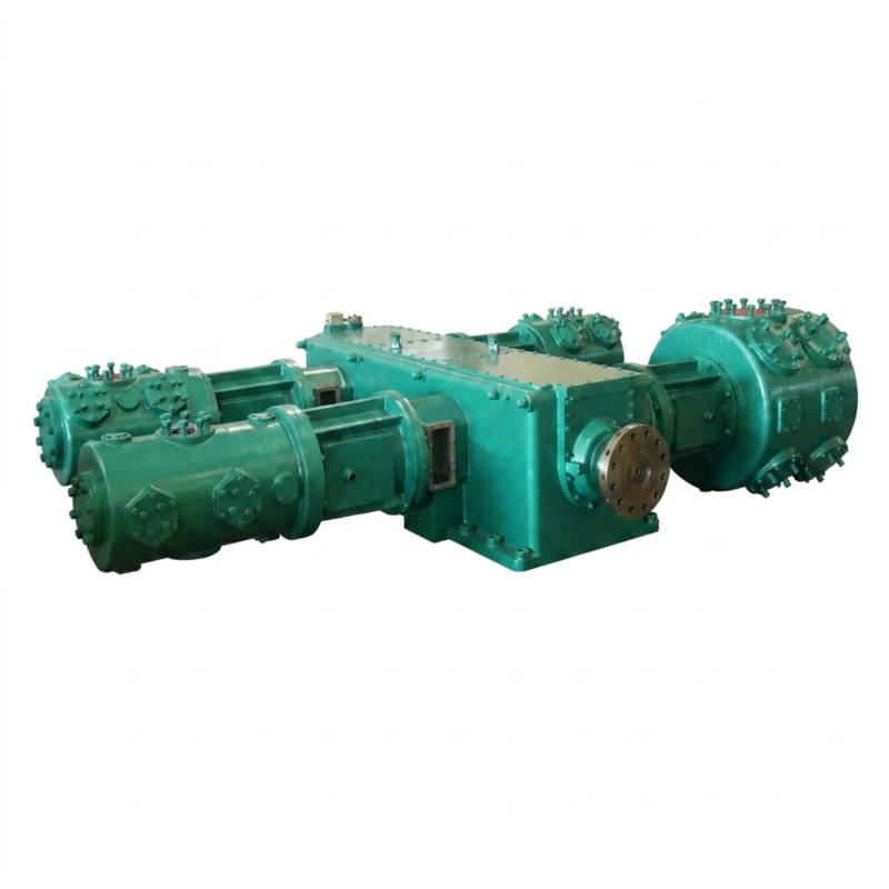
Engineering Challenges: What Makes LNG CO₂ Compression Difficult
CO₂ compression in LNG service combines the challenges of high-pressure process compression with the additional complexity of sour gas, variable feed composition, and the extreme reliability demands of a facility where every compressor is on the critical path.
Sour Gas: H₂S and Its Effect on Materials
The acid gas stream from an amine unit typically contains both CO₂ and H₂S. Even at very low H₂S concentrations — above a partial pressure of 0.0003 MPa as defined by NACE MR0175 / ISO 15156 — the gas is classified as sour and all metallic components in contact with the gas must comply with NACE materials requirements. This means carbon steel with hardness above Rockwell C22 is prohibited; weld heat-affected zones must be post-weld heat treated or meet hardness limits; and all pressure-retaining components must be selected from the NACE-approved materials list. For a high-pressure reciprocating compressor, this affects the cylinder material, piston rod, valve bodies, all connected piping and fittings, and the bolting on high-pressure flanges. NACE compliance for a complete compressor package is a significant engineering scope item that must be specified clearly in the enquiry.
Variable Feed Composition
The composition of the acid gas stream from the amine unit is not constant. As the amine solvent ages, as feed gas composition varies between wells, and as the amine unit operates at different loading conditions, the CO₂-to-H₂S ratio and the total acid gas flow rate change. The compressor must operate reliably across the full range of anticipated feed gas compositions without exceeding mechanical limits or losing capacity. This requires careful thermodynamic analysis covering all composition extremes — not just the design case — and a capacity control strategy that can respond to variations in inlet conditions.
Water Vapour and Hydrate Formation
The acid gas leaving the amine regeneration column is water-saturated at the regenerator temperature — typically 100°C to 120°C. As this gas cools during compression and in the interstage coolers, water condenses. In the presence of H₂S and CO₂, liquid water forms extremely corrosive carbonic and sulphurous acids that attack carbon steel at rates that can perforate piping within months. Additionally, at elevated pressures, CO₂, H₂S, and water can combine to form hydrates — ice-like solid compounds that block pipelines and valve passages without warning. The compressor inlet system must include robust water knockout facilities, and the interstage cooling and separation system must be designed to remove condensed water at every stage before the gas enters the next compression cylinder.
CO₂ Critical Point and Phase Behaviour
For high-CO₂ acid gas streams where CO₂ is the dominant component, the critical point of the gas mixture — the pressure and temperature above which the gas exists as a single supercritical phase — is close to that of pure CO₂ (31.1°C, 7.38 MPa). Compression stages passing through this region must be designed with conservative interstage cooling margins and high-efficiency liquid knockout to prevent liquid formation inside the compressor cylinder. Real-gas equations of state must be used for all thermodynamic calculations in this pressure range, as ideal-gas assumptions produce significant errors in predicted performance near the critical point.
Extreme Reliability Requirement
In an LNG plant, the CO₂ reinjection compressor is often a single-train machine with no installed spare. If it fails, the acid gas from the amine unit has nowhere to go, and the amine unit must be shut down. When the amine unit shuts down, the CO₂ content of the feed gas to the liquefaction train rises above the 50 ppm freeze-out limit, and the LNG train must be shut down within hours. The economic consequence of a forced LNG train shutdown — in terms of lost production, restartup costs, and potential penalty payments under long-term supply contracts — can reach tens of millions of dollars per day. This reality makes the CO₂ reinjection compressor one of the most reliability-critical machines in the entire facility.
Compressor Selection: Reciprocating vs Centrifugal for LNG CO₂ Service
The choice between reciprocating and centrifugal compressors for LNG CO₂ reinjection is determined by the required combination of flow rate, discharge pressure, and gas composition.
| Factor | Reciprocating Compressor | Centrifugal Compressor |
|---|---|---|
| Pressure range | Excellent to 25 MPa+ | Limited above 10 MPa |
| Flow range | 2–300 Nm³/min | 100–3,000+ Nm³/min |
| Variable composition tolerance | Good — positive displacement | Poor — sensitive to MW changes |
| Sour gas NACE compliance | Well-established practice | Complex dry gas seal requirements |
| Turndown capability | 30–100% with unloaders | Limited by surge line |
| Typical LNG application | High-pressure injection stages; small to medium flow plants | Low-pressure stages; large flow trains |
For LNG plants handling moderate acid gas volumes (2 to 150 Nm³/min) at reinjection pressures above 10 MPa, reciprocating compressors are the standard choice throughout the entire compression train. For very large LNG plants with high-CO₂ feed gas — such as the Gorgon LNG project in Australia or the Natuna development in Indonesia, where CO₂ volumes are measured in millions of tonnes per year — centrifugal compressors may be used for the lower-pressure stages (0.1 to 5 MPa), with reciprocating machines handling the high-pressure injection stages above 10 MPa where centrifugal compressors become impractical.
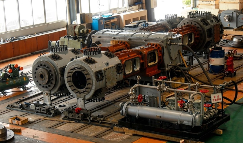
Key Specification Requirements for LNG CO₂ Reinjection Compressors
Based on the engineering challenges described above, the following specification requirements must be applied to reciprocating CO₂ compressors for LNG acid gas reinjection service.
All metallic components in contact with the sour acid gas — cylinders, heads, distance pieces, piston rods, valve bodies, interstage piping, and separators — must be specified and certified in NACE-compliant materials. The NACE materials requirement applies even when H₂S concentrations appear low, because H₂S partial pressure is what matters, not mole fraction: at a total pressure of 10 MPa, a gas containing 1% H₂S has an H₂S partial pressure of 0.1 MPa — more than 300 times the NACE threshold. All welds in sour service must be post-weld heat treated or comply with hardness limits, and weld procedure qualifications must include hardness testing. Material test certificates (MTCs) must be provided for all pressure-retaining components and archived for the life of the plant.
For LNG CO₂ reinjection compressors operating above 5 MPa on a critical process path, a full API 618 Chapter 3 pulsation and mechanical study is mandatory. The study must cover the complete piping system from the amine unit outlet to the wellhead injection manifold, including all interstage vessels, coolers, and connecting piping. The study must demonstrate compliance with API 618 pulsation and vibration limits across the full operating range, including minimum and maximum flow conditions and all anticipated gas compositions. The study results must be agreed with the plant owner before detailed piping design begins, because any pulsation dampener requirements or piping modifications identified by the study will affect the facility layout.
Beyond the NACE requirements for sour gas compliance, the combination of CO₂, H₂S, and water requires corrosion-resistant materials for all wetted pressure parts. Austenitic stainless steel (316L or duplex 2205) or higher-grade nickel alloys are specified for cylinder liners, interstage piping, separator internals, and cooler tubes. Valve bodies for the high-pressure stages must be in solid stainless steel or Inconel, not carbon steel with stainless steel trim. The use of dissimilar metal pairs that could promote galvanic corrosion must be avoided in all wetted areas. A comprehensive corrosion assessment covering all anticipated gas compositions should be included in the compressor engineering scope.
Compressing acid gas from 0.1 MPa to 15 to 25 MPa requires four to six compression stages, with interstage cooling and liquid knockout between every stage. The interstage separators must be sized for complete liquid dropout at all anticipated gas compositions and cooling water temperatures, including worst-case hot weather conditions when cooling water temperature is highest and liquid knockout is least effective. All interstage separators must have high-level liquid alarms and automatic emergency shutdown to prevent liquid carry-over into the next stage, which would cause hydraulic shock and compressor cylinder failure.
For sour gas service, a Type D double-compartment distance piece is mandatory. The inner compartment is purged with dry nitrogen or instrument air at a slightly positive pressure relative to the crankcase, preventing sour gas from migrating into the crankcase and contaminating the lubricating oil (which would cause foaming, corrosion of crankshaft bearings, and lube oil system degradation). The outer compartment is vented through a continuous vent line to a safe location — a vent header connected to the flare system, not to atmosphere, because H₂S in the vent stream is toxic even at low concentrations.
Given the toxic nature of H₂S in the acid gas stream and the critical-path position of the compressor in the LNG plant, a comprehensive safety instrumented system (SIS) is required. The SIS must provide automatic emergency shutdown (ESD) on: high-high discharge temperature per stage, high-high discharge pressure, low-low lube oil pressure, high-high frame vibration, liquid level in interstage separators, and H₂S gas detector alarm in the compressor enclosure. All SIS functions must be SIL-rated and tested in accordance with IEC 61511. The compressor control system must be able to initiate a safe and orderly shutdown without operator intervention in the event of any SIS trip, venting the compressor contents safely to the flare system.
Typical Specification Parameters for LNG CO₂ Reinjection Compressors
| Parameter | Typical Range | Design Note |
|---|---|---|
| Inlet pressure | 0.1–0.3 MPa | Amine unit regenerator overhead pressure |
| Discharge pressure | 10–25 MPa | Set by reservoir injection pressure plus wellbore hydrostatic losses |
| Number of stages | 4–6 stages | Max. compression ratio per stage 3:1 to 4:1 |
| Flow capacity | 2–300 Nm³/min | Determined by feed gas CO₂ content and LNG plant throughput |
| Feed gas CO₂ content | 40–90% CO₂ | Balance: H₂S, water vapour, trace hydrocarbons |
| H₂S content | 0.1–50% of acid gas | NACE MR0175 compliance required above 0.0003 MPa H₂S partial pressure |
| Frame type | M-Type or D-Type | M-Type preferred for continuous service and low vibration |
| Combined rod load | 50–150 T | Per API 618 combined rod load limits |
| Design life | 20–30 years | Matching the LNG plant operating life; spare parts commitment required |
Summary: LNG CO₂ Reinjection Compressor Specification Checklist
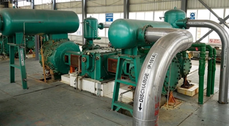
Frequently Asked Questions — CO₂ Compressors for LNG Plants
Discuss Your LNG CO₂ Compression Requirements
Our engineering team has extensive experience specifying and manufacturing reciprocating CO₂ compressors for LNG acid gas reinjection service to API 618 and NACE MR0175 requirements. Provide your gas composition and injection conditions and we will recommend the right configuration for your project.
Related Application Guides