
Overview: How CO₂ Compressors Enable Dry Ice Production
Dry ice — solid carbon dioxide at −78.5°C — is produced in industrial quantities for applications ranging from food preservation and cold-chain logistics to cryogenic cleaning, laboratory cooling, and entertainment effects. Unlike water ice, dry ice sublimates directly from solid to gas without passing through a liquid phase at atmospheric pressure, making it exceptionally useful for applications that must stay dry and where liquid meltwater would cause damage or contamination.
The production of dry ice begins with gaseous CO₂ that must be compressed and liquefied before it can be solidified and formed into blocks, pellets, or slices. The CO₂ liquefaction compressor is the first and most critical piece of process equipment in any dry ice production plant: it determines the throughput, the energy consumption, and ultimately the product purity of the entire operation. This guide explains how dry ice is made, what role the compressor plays, and how to specify the right compressor for a dry ice production facility.
How Dry Ice Is Made: The Production Process
The dry ice production process follows a defined sequence of steps, each of which depends on the preceding step being executed correctly. Understanding the full process chain is essential to understanding what the compressor must do and why its specification matters.
Step 1: CO₂ Source Gas Collection
The CO₂ used in dry ice production is typically recovered as a by-product from industrial processes: ammonia synthesis, hydrogen production, ethanol fermentation, power generation, or direct purchase of bulk liquid CO₂ from an industrial gas supplier. Source gas from fermentation or combustion typically arrives at near-atmospheric pressure (0.05 to 0.15 MPa) and may contain water vapour, trace hydrocarbons, and other impurities. Bulk liquid CO₂ from tanker delivery arrives already liquefied and simply requires vaporisation and recompression if further processing is needed. The purity of the source CO₂ is the most critical input variable in dry ice production: food-grade applications require 99.9% purity or better, with oil content below 0.1 ppm and contaminants such as benzene, acetaldehyde, and sulphur compounds at or below the limits defined by ISBT or relevant food safety standards.
Step 2: Purification and Dehydration
Before compression, the source CO₂ passes through an activated carbon bed to remove trace hydrocarbons and odour compounds, followed by a molecular sieve dryer to reduce the moisture content to a dew point of −40°C or lower. Dehydration is essential: water vapour in the CO₂ stream will freeze inside the compressor at low temperatures, blocking valve passages and causing mechanical damage. Activated carbon and molecular sieve beds are regenerated on a timed or differential pressure cycle, with twin-bed installations allowing continuous operation during regeneration.
Step 3: Compression to Liquefaction Pressure
The purified, dry CO₂ gas is compressed by a reciprocating piston compressor from its inlet pressure to the liquefaction pressure — typically 6 to 8 MPa. At this elevated pressure, CO₂ can be condensed into liquid form by cooling to ambient temperature or slightly below in a water-cooled or air-cooled condenser. The liquid CO₂ produced is stored in an insulated pressure vessel at approximately 6 to 7 MPa and −20°C, ready for the solidification step. This compression stage is the primary energy consumer in the dry ice production chain and the piece of equipment that most directly determines the plant’s operating cost and CO₂ throughput capacity.
Step 4: Expansion and Solidification
Liquid CO₂ from the storage vessel is passed through an expansion valve into a hydraulic press at atmospheric pressure. The sudden pressure reduction causes approximately 46% of the liquid CO₂ to flash into gas (which is recovered and recirculated to the compressor inlet), while the remaining 54% solidifies into dry ice snow at −78.5°C. The dry ice snow is then hydraulically compressed in the press to form blocks, pellets, or slices of the required density and dimension. Block dry ice is typically used for longer-duration cooling applications; pelletised dry ice for dry ice blasting and medical cold chain; sliced dry ice for food packing and laboratory use.
Compressor Specification for Dry Ice Production
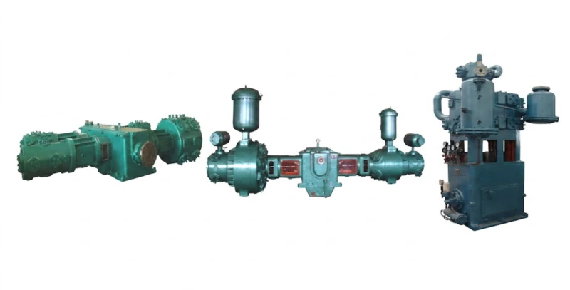
The CO₂ compressor for a dry ice plant must satisfy a specific set of requirements that reflect the combination of food-grade purity demands and the moderately high pressure required for CO₂ liquefaction. The following specifications define the essential requirements.
Discharge Pressure: 6 to 8 MPa
The required discharge pressure is determined by the liquefaction temperature achievable with the available cooling medium (cooling water or ambient air) and a safety margin above the CO₂ saturation pressure at that temperature. For a plant using cooling water at 25°C, CO₂ liquefaction occurs at a saturation pressure of approximately 6.4 MPa. The compressor is typically set to deliver at 6.5 to 7.5 MPa to ensure reliable liquefaction across all ambient temperature conditions. Plants in hot climates or using air cooling may require discharge pressures closer to 7.5 to 8 MPa to maintain adequate condensing driving force in summer conditions.
Oil-Free Cylinder Design: Non-Negotiable for Food-Grade Dry Ice
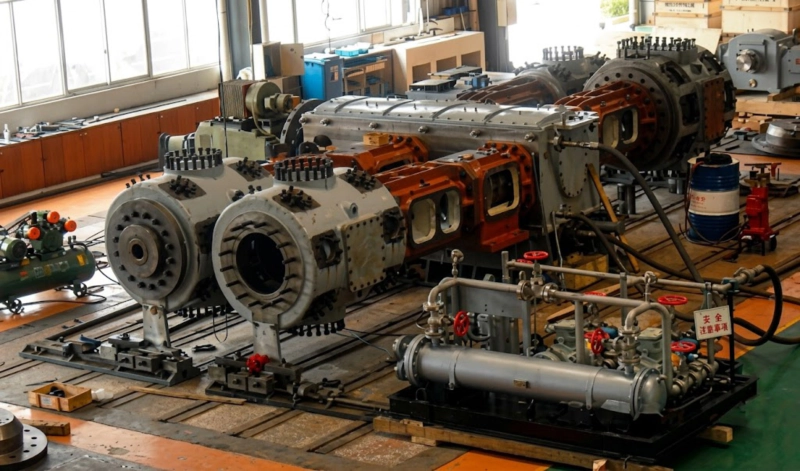
Dry ice produced for food contact, medical, or laboratory use must be manufactured from food-grade CO₂ with zero oil contamination. An oil-lubricated compressor introduces hydrocarbon lubricant into the CO₂ gas stream through the cylinder walls, piston rings, and rod packing, even with high-efficiency oil separators downstream. For food-grade dry ice production, this risk is not acceptable. The compressor must use oil-free cylinder design with PTFE or PEEK self-lubricating piston rings and packing seals, with a double-compartment distance piece isolating the crankcase from the compression circuit. The crankcase remains oil-lubricated for bearing protection, but no oil contacts the CO₂ gas stream at any point.
Compression Staging: Typically Two Stages
Compressing CO₂ from near-atmospheric pressure (0.1 MPa) to 7 MPa represents an overall compression ratio of 70:1 — far beyond what can be achieved efficiently in a single stage. The standard approach is two-stage compression: the first stage raises the pressure from inlet to an intermediate pressure of approximately 2 to 3 MPa, with an interstage cooler and separator to remove the heat of first-stage compression and any condensate before the second stage raises the pressure to the final liquefaction pressure of 6 to 8 MPa. Two-stage compression reduces the discharge temperature of each stage, improves volumetric efficiency, reduces total power consumption compared to single-stage compression of the same overall ratio, and makes the compressor more tolerant of variations in inlet pressure.
When liquid CO₂ at 6 to 7 MPa is expanded to atmospheric pressure in the dry ice press, approximately 46% of the liquid flashes to gas and 54% solidifies to dry ice snow. The flashed gas — known as flash gas or recycle gas — is recovered and returned to the compressor inlet to avoid waste. In a well-designed plant with flash gas recovery, the overall CO₂ conversion efficiency from compressed gas to dry ice product is typically 50 to 55%, with the balance of losses attributable to purge gas, dehydrator regeneration, and sublimation during handling and storage.
Flow Capacity: Sized to Plant Throughput
The required compressor flow capacity is determined by the target dry ice production rate. Since approximately 54% of the liquid CO₂ produced by the compressor converts to dry ice in the press, and allowing for the flash gas recycle, the compressor must handle approximately 1.8 to 2.0 Nm³ of CO₂ gas per kilogram of dry ice produced per hour. A plant producing 500 kg/h of dry ice therefore requires a compressor with a capacity of approximately 15 to 20 Nm³/min at the inlet conditions. Larger plants producing 2 to 5 tonnes of dry ice per hour require compressor capacities of 60 to 200 Nm³/min. These flow rates are well within the capability of Z-type and D-type reciprocating compressors.
| Plant Capacity | CO₂ Flow Required | Discharge Pressure | Typical Frame | Motor Power |
|---|---|---|---|---|
| 100–300 kg/h | 3–10 Nm³/min | 6–7.5 MPa | Z-Type, 2-stage | 15–45 kW |
| 300–1,000 kg/h | 10–35 Nm³/min | 6.5–8 MPa | Z or D-Type, 2-stage | 45–150 kW |
| 1,000–3,000 kg/h | 35–100 Nm³/min | 6.5–8 MPa | D-Type, 2-stage | 150–500 kW |
| 3,000–5,000+ kg/h | 100–200 Nm³/min | 7–8 MPa | D-Type or M-Type | 500–1,500 kW |
Dry Ice Applications and Their CO₂ Quality Requirements
Not all dry ice is produced to the same quality standard. The end application determines the CO₂ purity specification, which in turn influences the required upstream purification equipment and the importance of oil-free compression.
| Application | CO₂ Purity | Oil Limit | Oil-Free Compressor |
|---|---|---|---|
| Food packaging and preservation | ≥ 99.9% v/v | ≤ 0.1 ppm | Mandatory |
| Medical and pharmaceutical cold chain | ≥ 99.99% v/v | ≤ 0.05 ppm | Mandatory |
| Laboratory and research use | ≥ 99.9% v/v | ≤ 0.1 ppm | Mandatory |
| Dry ice blasting (industrial cleaning) | ≥ 99.5% v/v | ≤ 1 ppm | Strongly recommended |
| Stage effects and entertainment | ≥ 99% v/v | ≤ 5 ppm | Optional |
In practice, most commercial dry ice producers specify oil-free compression as standard, because a single production line typically serves multiple markets simultaneously, and the purity demands of the most stringent application — food or medical — determine the compressor specification for the entire plant. Retrofitting oil-free cylinders to an existing oil-lubricated compressor is technically complex and often uneconomical; specifying oil-free compression from the outset is always the lower-risk and more cost-effective approach.
Key Operational Considerations for Dry Ice Plant Compressors
Flash Gas Recycle Management
The approximately 46% of liquid CO₂ that flashes to gas in the dry ice press must be recovered and returned to the compressor suction to avoid waste and maintain plant economics. This flash gas recycle stream arrives at the compressor inlet at near-atmospheric pressure and at a temperature close to −78°C — the sublimation temperature of CO₂ at atmospheric pressure. The compressor inlet system must be designed to warm this cold recycle gas to a temperature above the dew point of any moisture present before it contacts the compressor suction valve, to prevent ice formation on valve seats and in suction passages. A suction scrubber with appropriate insulation and a gas warming arrangement is standard in dry ice plant compressor packages.
Capacity Control for Variable Production Demand
Dry ice plants rarely operate at full capacity around the clock. Demand for dry ice is inherently seasonal and cyclical — summer demand for food and beverage cold chain is higher than winter demand; special events create short-term demand spikes. The compressor must provide reliable capacity control across a wide production range, typically 30% to 100% of design capacity. Suction valve unloaders on individual cylinders allow step-wise capacity reduction in 25% or 33% increments on multi-cylinder compressors. Variable frequency drives provide continuous and smoother capacity modulation and are increasingly specified for new dry ice plant installations to optimise energy efficiency at part-load conditions.
Maintenance Planning for Continuous Production
Many dry ice production facilities operate on a near-continuous basis — 20 or more hours per day, six or seven days per week — to meet supply contracts and minimise unit production costs. This operating profile demands a compressor with a robust planned maintenance programme based on operating hours. For oil-free reciprocating CO₂ compressors in dry ice service, typical wear item replacement intervals are: piston rings and packing rings every 4,000 to 8,000 hours, gas valves every 6,000 to 10,000 hours, and piston rod inspection annually. Maintaining a recommended spare parts inventory on-site — including one complete set of piston rings, packing rings, and gas valves for each cylinder — eliminates the risk of extended downtime waiting for parts delivery.
Summary: Dry Ice Production CO₂ Compressor Specification Checklist
Frequently Asked Questions — CO₂ Compressors for Dry Ice Production
Discuss Your Dry Ice Plant Compression Requirements
Our engineering team specialises in oil-free reciprocating CO₂ compressors for dry ice production and liquefaction applications. Provide your production target and CO₂ source conditions and we will recommend the right compressor configuration for your plant.