
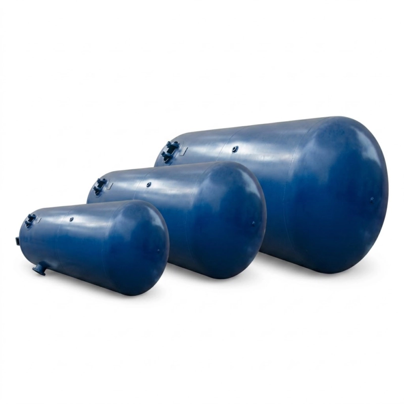
Pressure Vessels for Industrial Gas and Process Applications

Pressure vessels GB150 / ASME VIII / GOST R 52857, Class I–IV, 0.1–35 MPa, 10–200,000 L. CS, SS, alloy steel. Full certification. 4–16 week delivery.

Category:

Industrial Pressure Equipment · GB150 / ASME VIII · Class I – IV · Russia and Export

Pressure Vessels for Industrial Gas and Process Applications

Fabricated pressure vessels for compressed air systems, industrial gas storage, refrigerant service, process separation, and chemical plant duty. Class I and Class II pressure vessels per GB150, with ASME Section VIII Division 1 and GOST R 52857 variants available. Working pressures from 0.1 MPa to 35.0 MPa; vessel volumes from 10 litres to 200,000 litres; carbon steel, stainless steel, and alloy steel construction. Supplied with material certificates, pressure test records, and full certification documentation for Russian Rostechnadzor registration or export market requirements. Delivered from our fabrication facility with 4–16 week lead time depending on specification.

✓ GB150 / ASME VIII / GOST R 52857
✓ 0.1–35.0 MPa Working Pressure
✓ 10–200,000 Litre Volume
✓ CS / SS / Alloy Steel
✓ Rostechnadzor Documentation
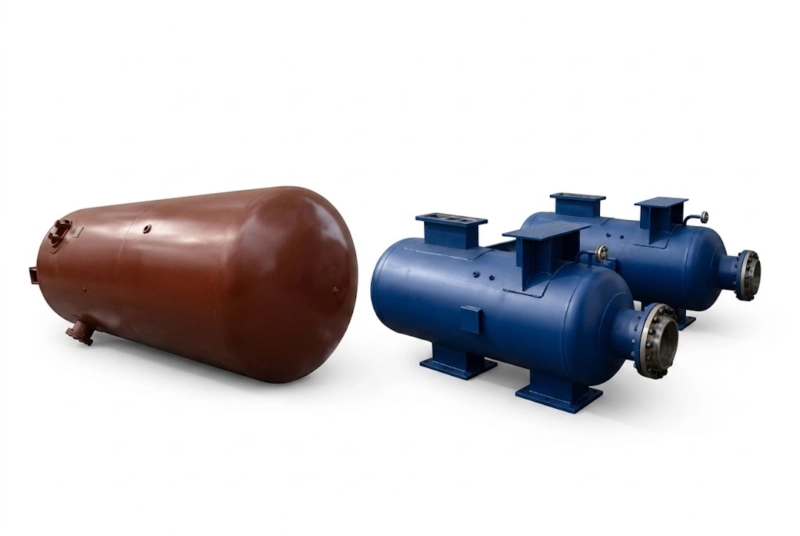
Class I and Class II pressure vessels GB150 carbon steel stainless steel industrial gas compressed air refrigerant process service fabrication

Class I and Class II pressure vessels — fabricated to GB150, ASME Section VIII, or GOST R 52857. Carbon steel, stainless steel, and alloy steel. Working pressures to 35.0 MPa; volumes from 10 to 200,000 litres. Full material certification and pressure test documentation supplied.

Class I–IV
Pressure Vessel Class
0.1–35.0 MPa
Working Pressure
10–200,000 L
Vessel Volume
GB150 / ASME
Design Standard
4–16 Weeks
Delivery

Product Overview: Industrial Pressure Vessels

A pressure vessel is a closed sealed container designed to hold gases or liquids at a pressure substantially different from the ambient pressure. In industrial gas and process plant service, pressure vessels serve as compressed air receivers, gas storage buffers, refrigerant separators, inter-stage cooler shells, oil separators, flash drums, scrubbers, and heat exchanger shells. Every industrial compressor installation requires at least one such vessel — the receiver tank or separator vessel downstream of the compressor — and large process plants may contain hundreds of pressure vessels of varying type, size, and pressure class within the plant battery limits.

Our fabrication programme covers four standard service categories: compressed air receivers for general industrial compressed air systems; separator and knock-out vessels for compressor inter-stage and discharge service; high-pressure storage vessels for nitrogen, oxygen, and industrial gas cylinder filling stations; and custom process pressure vessels for chemical, petrochemical, and refrigeration plant service. Each vessel is fabricated to the design standard, pressure class, and material specification required by the service conditions and the regulatory framework of the destination country — GB150 for Chinese market and export, ASME Section VIII Division 1 with U-stamp for North American and international project markets, and GOST R 52857 for Russian Rostechnadzor registration. All vessels leave our facility with hydrostatic pressure test records, material mill certificates, weld inspection records, and the documentation package required for equipment registration and commissioning at the installation site.

The classification system under GB150 divides pressure vessels into four classes based on the product of working pressure (MPa) and volume (m³) — the PV product — combined with the medium hazard level. Class I covers the lowest PV product with non-hazardous media; Class IV covers the highest PV product and hazardous media. The classification determines fabrication, inspection, and testing requirements, third-party inspection authority, and post-fabrication registration requirements before it can be placed in service. Our fabrication facility holds the relevant pressure vessel fabrication licences for Class I through Class IV vessels, and our engineering and documentation team manages the certification process from design through to final handover.

Pressure Vessel Types and Standard Specifications

The table below covers the standard pressure vessel configurations available from our fabrication programme. Non-standard dimensions are accommodated on a project basis.

Type Volume (L) Working Pressure (MPa) Material Standard Class
Compressed Air Receiver 100–50,000 0.8–1.3 Q345R / A516-70 GB150 / ASME VIII I – II
N₂ / O₂ High-Pressure Buffer 50–5,000 5.0–35.0 35CrMo / Cr-Mo alloy GB150 / ASME VIII III – IV
Oil Separator Vessel 20–2,000 0.8–4.0 Q345R / 304 SS GB150 I – II
Inter-Stage Moisture Separator 10–500 0.5–20.0 Q345R / 316L SS GB150 / ASME VIII I – III
Refrigerant Liquid Receiver 100–20,000 1.6–2.5 Q345R (NH₃ rated) GB150 / GOST R 52857 II – III
Flash Vessel / Economiser 50–5,000 0.3–1.6 Q345R (copper-free for NH₃) GB150 / GOST R 52857 I – II
Process Knock-Out Drum 200–200,000 0.1–6.4 Q345R / 304 SS / 316L GB150 / ASME VIII I – III
Air Tank / Oil-Separator Combination 50–2,000 0.8–1.6 Q345R GB150 I – II

All pressure vessel dimensions and wall thicknesses are calculated per the applicable design standard for the stated working pressure and material specification. Nozzle sizes, flange ratings, and head types are project-specific. MAWP is determined by the design calculation and stated on the nameplate. Hydrostatic test pressure is 1.25 × MAWP (ASME VIII) or 1.25 × design pressure (GB150).

Standard Design and Fabrication Parameters

Parameter Pressure Vessel — Standard Range
Design Standards GB150 (China); ASME Section VIII Div. 1 (International); GOST R 52857 (Russia / EEU)
Working Pressure Range 0.1 MPa to 35.0 MPa (full vacuum to 35 MPa for special grades)
Volume Range 10 litres to 200,000 litres per vessel; multi-vessel systems available
Shell Materials Q345R (carbon steel); 304 / 316L SS; 321 SS; 35CrMo; Cr-Mo alloy P11/P22; duplex 2205
Head Type Ellipsoidal (2:1); hemispherical; torispherical; flat (low-pressure small vessels)
Design Temperature −50°C to +450°C depending on material grade
Weld Inspection RT (100% or spot per class); UT; PT / MT for nozzle-to-shell welds and heads
Pressure Testing Hydrostatic at 1.25 × MAWP (ASME) or 1.25 × design pressure (GB150); pneumatic test on request
Surface Treatment Internal: bare, epoxy-coated, or stainless-clad per service. External: primer + topcoat or hot-dip galvanised
Documentation Mill certificates, WPS/PQR, welder qualifications, NDE reports, hydro test records, MAWP nameplate, data report
Lead Time 4–8 weeks (standard sizes, Class I–II); 8–16 weeks (Class III–IV, special materials, large volume)

Pressure Vessel Design and Fabrication Process
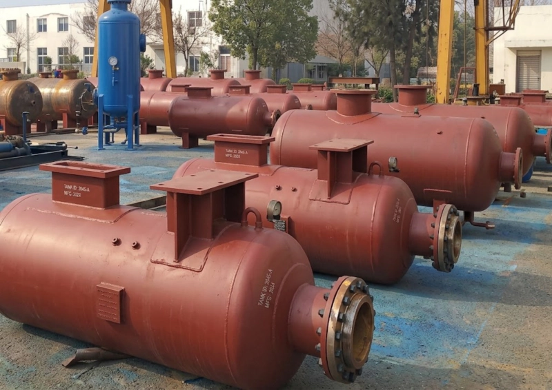
pressure vessels awaiting shipment after fabrication hydrostatic testing and inspection carbon steel industrial gas storage compressed air

Every vessel fabricated at our facility follows a documented production sequence that begins with design calculation and ends with hydrostatic test and documentation handover. The design is performed by our in-house engineering team using the applicable design standard — GB150-2011, ASME Section VIII Division 1, or GOST R 52857. The design calculation determines the minimum required shell wall thickness, head thickness, nozzle reinforcement areas, and flange ratings for the stated design pressure, design temperature, and corrosion allowance. Material selection is verified against the allowable stress tables of the applicable standard at the design temperature, and any material substitutions from the client specification are documented and approved before fabrication begins.

Shell plate and head material is ordered to the specified grade with mill test reports (MTRs) and certified to the relevant material standard — GB713 for Q345R carbon steel, ASTM A516 Grade 70 for ASME vessels, or GOST 5520 for Russian service. Plates are marked, cut, and rolled to the calculated shell diameter. Longitudinal and circumferential seam welds are performed by qualified welders to approved welding procedure specifications (WPS). All pressure vessel weld joints are subject to non-destructive examination — radiographic testing (RT) for full or spot examination of seam welds depending on class and standard, with ultrasonic testing (UT) as the alternative for thick-wall vessels, and magnetic particle or liquid penetrant testing (MT/PT) for nozzle-to-shell attachment welds and head knuckle areas. Completed vessels undergo hydrostatic testing at 1.25 times the maximum allowable working pressure, with a hold period and inspection for leaks and deformation. The complete quality dossier is compiled and handed over with each vessel.

Design Calculation
Shell wall thickness, head geometry, nozzle reinforcement, and flange rating calculated to GB150, ASME VIII, or GOST R 52857. Corrosion allowance, wind and seismic loads, and support saddle loads included where applicable. Design documentation retained and supplied with the pressure vessel dossier.
Certified Materials
All pressure-retaining materials are ordered with mill test reports certified to the applicable material standard. Traceability from mill certificate to final pressure vessel nameplate is maintained throughout fabrication. No uncertified material is used in any pressure-retaining component of the pressure vessel.
NDE and Inspection
Radiographic testing (RT) of longitudinal and circumferential seam welds; UT for thick-wall vessels; MT or PT for nozzle attachment welds. Inspection performed by certified Level II or Level III NDE personnel. Reports are included in the pressure vessel documentation package.
Hydrostatic Test
Every pressure vessel is hydrostatically tested at 1.25 times MAWP with calibrated gauges traceable to national standards. The test is held for a minimum 30-minute inspection period. The test record — pressure, hold time, and inspector signature — is included in the documentation package supplied with every pressure vessel.

Pressure Vessel Application Scenarios
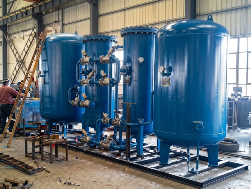
oil separator and air tank combination pressure vessel for screw compressor system compressed air storage industrial

🏭Compressed Air System — Receiver Tanks and Oil Separators

Every screw compressor and reciprocating compressor installation requires a receiver pressure vessel downstream of the compressor unit. The compressed air receiver serves as a pressure buffer, reducing compressor cycling in fixed-speed systems; as a moisture drop-out vessel where temperature reduction after the aftercooler causes condensation; and as a storage buffer that allows instantaneous demand peaks to be met without the compressor running at full capacity continuously. Standard compressed air receivers from 100 litres at 0.8 MPa for small workshop installations to 50,000 litres at 1.3 MPa for large manufacturing compressed air supply systems are available from our fabrication programme, with standard dished end / cylindrical shell construction in Q345R carbon steel, internal epoxy coating or bare steel, and ASME flanged connections.

🏭Compressor Inter-Stage and Discharge Service

Multi-stage reciprocating compressors of the ZW, DW, and LW series nitrogen and oxygen compressor range and the 4MW and DW series refrigerant compressor range require inter-stage cooler shells, inter-stage moisture separator vessels, and oil separator vessels as integral parts of the compression system. These vessels operate at intermediate pressures between compression stages, at temperatures from ambient to the maximum inter-stage discharge temperature. Our fabrication programme produces inter-stage vessels sized and rated for the specific compressor model, with nozzle sizes and connection orientations matched to the compressor inter-stage pipework layout. For the high-pressure nitrogen and oxygen compressor series, inter-stage separators at 5.0–20.0 MPa are fabricated in Cr-Mo alloy steel with 100% RT of all seam welds and PWHT where required by the design standard.

🏩Industrial Refrigeration — NH₃ Receivers, Flash Vessels, and Separators

Industrial NH₃ refrigeration systems associated with our DW and 4MW series compressors require multiple vessels as standard plant items: high-pressure liquid receivers that store condensed ammonia at condensing pressure; low-pressure receivers or suction accumulators at evaporating pressure; flash vessels that act as economisers between high-stage and low-stage compressor suction; oil pots at low points in the ammonia circuit where oil accumulates; and suction knockout drums upstream of compressor suction nozzles that prevent liquid carry-over. All NH₃ pressure vessels in our programme are fabricated from copper-free materials — Q345R carbon steel with steel nozzles and flanges throughout — as required by the chemical incompatibility of ammonia with copper, copper alloys, and zinc. Each NH₃ refrigerant vessel is supplied with GOST R 52857 certification documentation for Rostechnadzor registration under Federal Law 116-FZ.

⚙️Industrial Gas Storage — High-Pressure N₂ and O₂ Buffer Vessels

Nitrogen and oxygen compressor installations at air separation plants and cylinder filling stations require high-pressure buffer storage vessels at the compressor discharge to smooth the cylinder filling cycle and provide a gas supply reserve during compressor downtime. These pressure vessels operate at 5.0–30.0 MPa in nitrogen service and up to 15.0 MPa in oxygen service. High-pressure nitrogen storage vessels are fabricated in 35CrMo or Cr-Mo alloy steel with wall thicknesses from 30 mm to 100 mm depending on the design pressure and vessel diameter. Oxygen storage vessels require additional fabrication controls: oxygen-degreased assembly, stainless steel nozzle liners, and material selection verified against the oxygen compatibility requirements of GOST 12.2.052 and the applicable pressure vessel standard.

Pressure Vessel Material Selection Guide
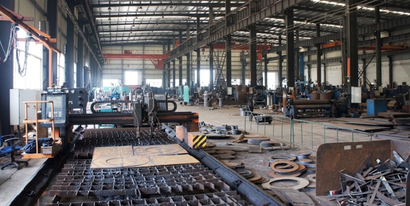
pressure vessel fabrication workshop showing vessels under construction welding inspection quality control industrial gas process equipment

Service Recommended Material Notes
Compressed air, N₂ to 10 MPa Q345R / A516-70 Standard carbon steel; lowest cost; suitable to +350°C
N₂ / O₂ at 10–35 MPa 35CrMo / P11 Cr-Mo alloy High-strength alloy for thick-wall high-pressure vessels; PWHT required
NH₃ refrigerant service Q345R (copper-free throughout) No copper, brass, or zinc in any wetted component; carbon steel flanges and nozzles
O₂ service to 15 MPa Q345R / 304 SS (O₂-cleaned) Oxygen-degreased assembly; stainless nozzle liners; no hydrocarbon lubricant in contact
Corrosive process service 304 / 316L / 321 SS; duplex 2205 Material grade depends on process fluid pH, chloride content, and temperature
Low-temperature service (below −20°C) 09MnNiDR / A516-70 normalised; 304L SS Notch toughness Charpy impact tested at minimum design temperature
High-temperature service (above 350°C) 12Cr1MoV / P22 / 321 SS Creep-resistant alloy grades; PWHT and post-weld hardness limits apply

FAQ — Pressure Vessel

Q1: What is the difference between Class I, II, III, and IV pressure vessels under GB150?
The pressure vessel class under GB150 is determined by two factors: the PV product (design gauge pressure in MPa multiplied by vessel volume in m³) and the hazard level of the contained medium. Class I covers non-toxic, non-flammable media at the lowest PV products (typically below 2.5 MPa·m³). Class II covers moderate PV products or more hazardous media at lower PV. Class III covers higher PV products or toxic / flammable media. Class IV covers the most hazardous combinations of high PV and toxic or high-pressure media. The class determines the extent of weld examination (spot RT for Class I; 100% RT or UT for Class III and IV), the third-party inspection requirements, and the post-fabrication registration process. A compressed air receiver at 0.8 MPa and 1 m³ (PV = 0.8) is typically Class I. An ammonia vessel at 1.6 MPa and 5 m³ (PV = 8.0) with a toxic medium may be Class III.
Q2: What documentation is supplied with each pressure vessel?
Every vessel from our facility is delivered with a complete quality and certification dossier that includes: the design calculation report; material mill test reports (MTRs) for all pressure-retaining parts; welding procedure specifications (WPS) and procedure qualification records (PQR); welder performance qualification records; NDE reports (RT or UT films and written reports; MT or PT reports for nozzle welds); hydrostatic pressure test record; nameplate rubbing or photograph showing MAWP, design temperature, serial number, and applicable standard; and the manufacturer data report. For Russian delivery, the dossier also includes the passport (tekhnicheskiy pasport) for Rostechnadzor registration; for ASME-stamped vessels, the U-1 data report and Authorised Inspector signatures are included.
Q3: What is MAWP and how does it relate to working pressure?
MAWP (Maximum Allowable Working Pressure) is the maximum gauge pressure at which the pressure vessel is permitted to operate, determined by the weakest element of the vessel — typically the shell, head, or a nozzle — at the design temperature. The MAWP may be equal to or greater than the design pressure stated in the purchase specification; it is stamped on the nameplate after fabrication and pressure testing. The working pressure (the actual operating pressure in service) must always remain below the MAWP. The hydrostatic test is performed at 1.25 times the MAWP to verify that the vessel can safely withstand an overpressure event without failure. The safety valve setting on the vessel must be at or below the MAWP.
Q4: What information is needed to obtain a pressure vessel quotation?
To prepare a pressure vessel proposal, provide: the service medium (gas or liquid type); design pressure (MPa) and design temperature (°C); vessel internal volume (litres or m³) or shell diameter and tangent-to-tangent length; shell material specification or acceptable equivalent; head type (ellipsoidal, hemispherical, or other); nozzle count and approximate sizes; applicable design standard (GB150, ASME VIII, or GOST R 52857); pressure vessel class if known; any special requirements (low-temperature toughness, PWHT, internal coating, oxygen service degreasing); and the delivery location. For compressor-related pressure vessels — inter-stage separators, oil separators, or refrigerant vessels associated with our compressor products — providing the compressor model number and service conditions is sufficient for our engineering team to propose the correct pressure vessel specification. Response within 48 hours.
Q5: How is a pressure vessel registered with Rostechnadzor in Russia?
Pressure vessels operating above 0.07 MPa with hazardous media — including ammonia, flammable gases, and certain process fluids — must be registered with Rostechnadzor as hazardous production objects under Federal Law 116-FZ before they are placed in service in Russia. Registration requires submission of the pressure vessel technical passport (pasport), the design calculation, the fabrication certificate (svidetelstvo ob izgotovlenii), and the installation organisation documentation to the local Rostechnadzor office. Our pressure vessels delivered to Russia include the technical passport and fabrication certificate structured to support this registration process. For compressed air receivers and nitrogen service pressure vessels at standard industrial pressures with non-hazardous media, Rostechnadzor registration is typically not required, though the vessel must still comply with the Russian technical regulations for pressure equipment (TR TS 032/2013).
Q6: Can you supply pressure vessels for oxygen service?
Yes. Oxygen service pressure vessels require specific fabrication controls beyond standard industrial gas vessels. The key requirements are: no hydrocarbon lubricants or oil-contaminated materials used in any component that will contact the oxygen; internal surfaces and all oxygen-wetted nozzle bores are degreased and cleaned to a hydrocarbon residue level below 50 mg/m³ before final assembly; stainless steel nozzle liners or stainless internal surfaces are used in areas of high velocity where particle impact ignition risk is elevated; all seals and gaskets are verified as oxygen-compatible (PTFE or oxygen-rated fluoroelastomers rather than standard nitrile); and the fabricated pressure vessel is sealed after degreasing and shipped with a nitrogen blanket to prevent contamination during transport. Oxygen service pressure vessels are supplied with oxygen equipment certification per GOST 12.2.052 for Russian delivery. Contact our engineering team with the oxygen purity, pressure, temperature, and vessel volume for a specification review.

Request a Pressure Vessel Quotation

Our engineering and fabrication team supplies pressure vessels for compressed air systems, industrial gas storage, industrial refrigeration, and process plant service across Russia and export markets. Class I through Class IV fabrication; GB150, ASME Section VIII, and GOST R 52857 standards; carbon steel, stainless steel, and alloy steel; full documentation for Rostechnadzor registration. Pressure vessels for compressor inter-stage, oil separation, and refrigerant service matched to all compressor models in our product range.

Pressure Vessel — Engineering Enquiry

Discuss Your Pressure Vessel Requirement

Pressure vessel engineers respond to all enquiries within 48 hours. GB150, ASME VIII, and GOST R 52857 documentation included as required.

Request a Quote

Include in Your Pressure Vessel Enquiry
✓ Service medium (gas or liquid type)
✓ Design pressure (MPa) and temperature (°C)
✓ Volume (litres) or shell diameter and length
✓ Material preference (CS / SS / alloy)
✓ Design standard (GB150 / ASME / GOST)
✓ Special requirements (O₂ service, low temp, coating)
✓ Nozzle count and approximate sizes
✓ Required delivery date and destination