
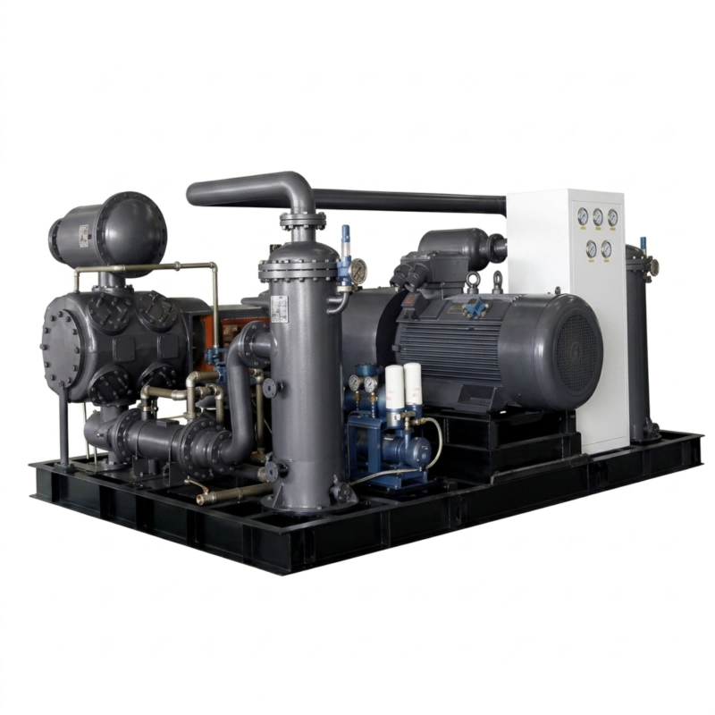
DW Series Gas Compressor
DW series gas compressor: 40–400 m³/min, 0.15–2.50 MPa, 22 models, API 618, GOST-R. Coal gas, coke oven gas, CO, biogas. Russia manufacturer. ATEX IIC available.
Gas Compression · Opposed-Balance Design · API 618 · Russia Manufacturer
DW Series Gas Compressor
Two-column horizontal opposed-balance reciprocating compressor for gas pipeline transmission, low-pressure process gas, flue gas, water gas, CO, coal gas, biogas, methane, and mixed industrial gas. 22 standard models spanning 40–400 m³/min at 0.15–2.50 MPa, with an extended four-column (4MW/HW) range reaching 400 m³/min and 2,300 kW. Manufactured to API 618 Fifth Edition and GOST-R at our production facility in Russia.
✓ GOST-R Certified
✓ ISO 9001:2015
✓ 22 Standard Models
✓ Russia and CIS Service
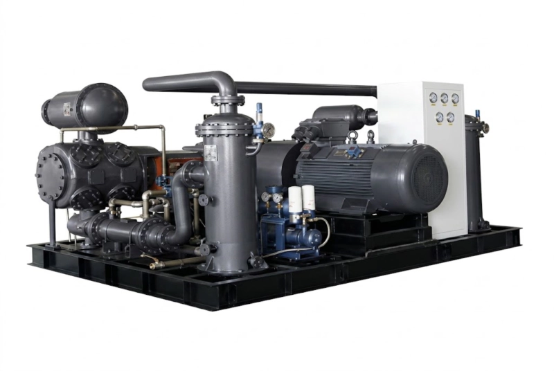
DW Series — Two-column horizontal opposed-balance reciprocating gas compressor. 22 standard models cover 40–400 m³/min at 0.15–2.50 MPa for gas pipeline, low-pressure process, and industrial gas transmission duties.
Product Overview: DW Series Gas Compressor
The DW series gas compressor is a two-column horizontal opposed-balance (opposed-balance) reciprocating piston compressor engineered for the compression of flammable, corrosive, and mixed industrial gases at large volumetric flow rates and low-to-medium pressures. The opposed-balance configuration — with pistons on opposite sides of the crankshaft moving in opposite directions simultaneously — is the defining feature of the DW series, cancelling the primary inertia forces that are the main source of vibration and foundation loading in reciprocating machines at high power levels.
The DW series is specified for gas media including: coal gas (city coal gas), coke oven gas (coke oven gas), blast furnace gas (blast furnace gas), flue gas (flue gas), water gas (water gas), carbon monoxide (CO), biogas (biogas), methane (methane), mixed refinery gas, and similar industrial process and utility gases. The compression medium can contain hydrogen, hydrocarbons, moisture, and incondensable components in varying proportions — the DW series material and sealing specification is selected at the engineering stage to match the specific gas composition of each installation.
22 standard models span 40 to 400 m³/min in flow rate and 0.15 to 2.50 MPa in discharge pressure. The two-column DW models (40–300 m³/min) handle the majority of pipeline transmission and low-pressure process duties. The four-column HW and 4MW extended models (250–400 m³/min, up to 2,300 kW) cover the highest-flow, highest-power duties in the range. All models require 6 kV or 10 kV drive voltage and are available with ATEX explosion-proof electrical equipment for flammable gas service. Manufactured at our production facility in Russia to API 618 Fifth Edition and GOST-R requirements with full Rostechnadzor documentation as standard.
Typical applications: City gas network compression stations, coke oven gas recovery and transmission, blast furnace gas boosting, coal chemical plant mixed gas compression, biogas upgrading plant feed compression, CO gas compression for chemical synthesis, industrial refinery off-gas recovery, mine gas drainage and surface compression, and large-volume process gas transfer.
The Opposed-Balance Advantage at High Gas Flow
At the power levels of the DW series — 355 to 2,300 kW — the dynamic forces generated by reciprocating pistons become a primary engineering constraint. In a single-column or same-direction machine, all pistons move in the same direction at the same moment, producing a large oscillating net force that must be absorbed entirely by the foundation. For a 1,200 kW machine, this net primary force can exceed 150 kN, requiring a foundation mass of 60–100 tonnes and special isolation systems.
In the DW opposed configuration, the pistons on opposite column sides move in opposing directions, and their primary inertia forces cancel at the crankshaft. The result is a net primary force close to zero — the compressor frame transmits only the residual secondary forces and gas pressure reactions to the foundation. Foundation mass is reduced by 50–70% compared to non-balanced designs at the same power, vibration levels transmitted to adjacent pipework and structures are substantially lower, and noise radiated from the compressor frame is reduced. For gas pipeline compressor stations and industrial plants where the compressor is located within or adjacent to existing buildings, this balance advantage frequently determines whether an expansion project is feasible within the existing civil structure.
Technical Specifications — DW Series Low Pressure (0.15–1.00 MPa)
Single-stage two-column configuration for gas pipeline transmission, large-volume low-pressure process gas duties, and industrial gas transfer. The application note on this group: gas media include coal gas, coke oven gas, flue gas, water gas, CO, biogas, methane, and mixed gas with hydrogen content up to 75%.
| Model | Config | Flow (m³/min) | Pressure (MPa) | Dimensions L×W×H (mm) | Weight (t) | Power (kW) | Voltage |
|---|---|---|---|---|---|---|---|
| DW-60/8 | 2-col 1-stage | 60 | 0.80 | 5000×1450×3300 | 6.50 | 400 | 6K/10K |
| DW-70/8 | 2-col 1-stage | 70 | 0.80 | 6000×2050×2525 | 13.00 | 450 | 6K/10K |
| DW-100/4 | 2-col 1-stage | 100 | 0.40 | 5456×3518×2535 | 13.00 | 450 | 6K/10K |
| DW-100/8 | 2-col 1-stage | 100 | 0.80 | 5456×3518×2535 | 13.50 | 630 | 6K/10K |
| DW-120/1.5 | 2-col 1-stage | 120 | 0.15 | 5000×1650×2450 | 6.20 | 355 | 6K/10K |
| DW-120/4 | 2-col 1-stage | 120 | 0.40 | 5600×3540×2550 | 13.00 | 550 | 6K/10K |
| DW-120/8 | 2-col 1-stage | 120 | 0.80 | 6000×3640×3000 | 18.00 | 630 | 6K/10K |
| DW-150/2.5 | 2-col 1-stage | 150 | 0.25 | 6250×2100×2735 | 15.00 | 500 | 6K/10K |
| DW-150/4 | 2-col 1-stage | 150 | 0.40 | 6250×2100×2735 | 17.00 | 710 | 6K/10K |
| DW-200/2.5 | 2-col 1-stage | 200 | 0.25 | 6250×2100×2735 | 15.00 | 680 | 6K/10K |
| DW-248/1.5 | 2-col 1-stage | 248 | 0.15 | 6250×2100×2735 | 14.00 | 630 | 6K/10K |
| DW-300/2.5 | 2-col 1-stage | 300 | 0.25 | 7200×3505×2820 | 27.00 | 1,200 | 6K/10K |
Note: All low-pressure DW models are single-stage. Pressure notation /8 = 0.80 MPa, /4 = 0.40 MPa, /2.5 = 0.25 MPa, /1.5 = 0.15 MPa. All dimensions L×W×H in mm.
| Model | Config | Flow (m³/min) | Pressure (MPa) | Dimensions (mm) | Weight (t) | Power (kW) |
|---|---|---|---|---|---|---|
| HW-400/2.5 | 4-col 1-stage | 400 | 0.25 | 6250×7200×2735 | 30.00 | 1,400 |
| HW-400/4.5 | 4-col 2-stage | 400 | 0.45 | 6250×7300×2820 | 34.00 | 1,200 |
| 4MW-250/4.5 | 4-col 2-stage | 250 | 0.45 | 7200×7300×2820 | 36.00 | 1,400 |
Technical Specifications — DW Series Mid-High Pressure (1.30–2.50 MPa)
Multi-stage configurations for chemical process gas compression, mid-pressure pipeline injection, and high-flow chemical synthesis gas feed at 1.3–2.5 MPa. Application note: gas media include high-hydrogen gas, flue gas, CO, coal gas, biogas, methane, and mixed gas with higher-pressure discharge requirements for chemical processes.
| Model | Config | Flow (m³/min) | Pressure (MPa) | Dimensions L×W×H (mm) | Weight (t) | Power (kW) | Voltage |
|---|---|---|---|---|---|---|---|
| DW-40/25 | 2-col 3-stage | 40 | 2.50 | 6585×3595×2095 | 13.00 | 450 | 6K/10K |
| DW-50/25 | 2-col 3-stage | 50 | 2.50 | 6585×3595×2095 | 13.00 | 500 | 6K/10K |
| DW-60/25 | 2-col 4-stage | 60 | 2.50 | 8500×2440×3020 | 17.00 | 600 | 6K/10K |
| DW-70/25 | 2-col 4-stage | 70 | 2.50 | 8500×2440×3020 | 17.00 | 710 | 6K/10K |
Note: /25 suffix indicates 2.50 MPa discharge pressure (25 bar). DW-60/25 and DW-70/25 use 4-stage compression to achieve the 2.5 MPa discharge from near-atmospheric suction in a single machine. All dimensions L×W×H in mm.
| Model | Config | Flow (m³/min) | Pressure (MPa) | Dimensions (mm) | Weight (t) | Power (kW) |
|---|---|---|---|---|---|---|
| 4MW-80/25 | 4-col 3-stage | 80 | 2.50 | 6500×6500×3200 | 26.00 | 800 |
| 4MW-180/16 | 4-col 3-stage | 180 | 1.60 | 7800×8000×2700 | 37.00 | 1,800 |
| 4MW-230/25 | 4-col 3-stage | 230 | 2.50 | 8000×8000×2700 | 40.00 | 2,300 |
The 4MW-230/25 at 230 m³/min and 2,300 kW is the highest-power single-machine configuration in the DW/4MW range. All 4MW/HW models require 6 kV or 10 kV supply and custom foundation design.
General Series Parameters
| Parameter | DW Series Specification |
| Compression Media | Coal gas, coke oven gas, blast furnace gas, flue gas, water gas, CO, biogas, methane, mixed industrial gas, hydrogen-containing gas |
| Discharge Pressure | 0.15–1.00 MPa (low pressure group); 1.30–2.50 MPa (mid-high pressure group) |
| Flow Range | 40–400 m³/min (2,400–24,000 Nm³/h) |
| Motor Power | 355–1,200 kW (DW 2-col); up to 2,300 kW (4MW 4-col) |
| Drive Voltage | 6 kV or 10 kV throughout (all models) |
| Frame Configuration | 2-column horizontal opposed-balance; 4-column (HW/4MW) for high-flow extended range |
| Compression Stages | 1-stage (low pressure); 2, 3, or 4-stage (mid-high pressure) |
| Cylinder Lubrication | Oil-lubricated standard; oil-free (PTFE rings) for clean gas or purity-critical service |
| Cooling Method | Water-cooled standard (cylinder jackets, intercoolers, aftercooler) |
| Electrical (flammable gas) | ATEX Zone 1 explosion-proof; Group IIA (methane, CO), IIB (coke oven gas), IIC (H₂-rich gas) |
| Design Standard | API 618 Fifth Edition; GOST-R (Russia / CIS) |
| Certification | ISO 9001:2015, GOST-R, ATEX, Pressure Vessel License |
Working Principle and Structural Composition
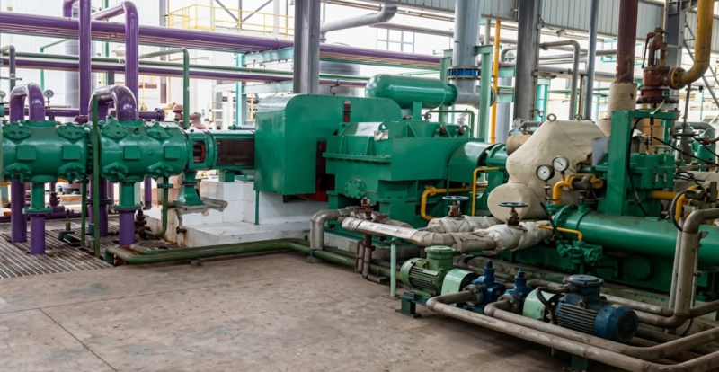
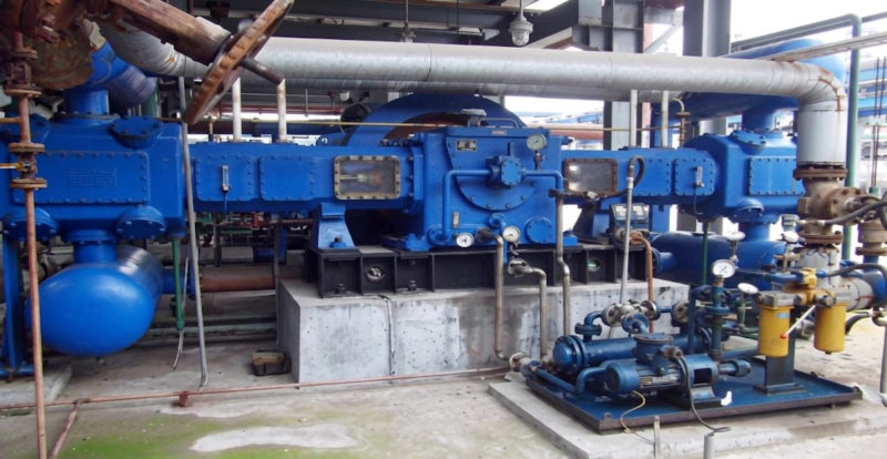
The DW series uses the horizontal opposed-balance reciprocating piston principle. A high-voltage motor drives the crankshaft, which has its two crank throws arranged 180 degrees apart. As one column’s piston moves forward on its compression stroke, the piston on the opposite column simultaneously moves backward on its suction stroke — the inertia forces of the two pistons oppose and largely cancel each other, leaving only the residual secondary forces and gas pressure reactions to be transmitted to the foundation.
For the single-stage low-pressure DW models, each column’s cylinder handles half of the total gas flow independently: suction gas enters both cylinders on their respective suction strokes, is compressed to discharge pressure, and both discharge streams combine at a common outlet header. For the multi-stage mid-high-pressure DW models, the two columns operate as sequentially staged compressors — the larger-bore LP column compresses from suction to interstage pressure, and the smaller-bore HP column receives interstage gas through the intercooler and compresses to final discharge pressure. Four-stage machines (DW-60/25, DW-70/25) achieve the 2.50 MPa discharge from near-atmospheric suction by adding two tandem cylinder bores to each column, providing four compression steps in a single machine pass.
Key Structural Components
Gas Media Guide: Materials and Safety Requirements by Gas Type
The DW series serves a wide range of flammable and industrial gas compositions. Each gas type has specific engineering requirements that are incorporated into the compressor specification at the design stage. The following guide covers the primary gas types in the DW series application range.
Core Advantages of the DW Series
Material Specifications
| Component | Standard Gas Service | Corrosive / H₂-Rich / H₂S Service |
|---|---|---|
| Frame / Crankcase | HT250 grey cast iron | HT250 (no change — isolated from gas) |
| Cylinders | HT250 cast iron with water jackets | 316L SS or alloy steel; NACE MR0103 for H₂S |
| Piston Rings / Packing | PTFE (oil-free) or cast iron (lubricated) | PTFE oil-free recommended; PEEK for elevated temp |
| Piston Rods | 42CrMo, hard chrome plated | Inconel overlay or 316L SS for H₂S service |
| Gas Valve Bodies | Carbon steel or 316L SS | 316L SS mandatory for wet or corrosive gas |
| Intercoolers / Aftercooler | Carbon steel shell; CS tubes | 316L SS tube bundle for wet or H₂S-containing gas |
| Distance Piece | Type C per API 618 | Type D with N₂ purge for CO, H₂S, or toxic gas |
| Electrical Equipment | ATEX Zone 1, Group IIA or IIB | ATEX Zone 1, Group IIC for H₂ above 25% |
Selection Guide: Choosing the Right DW Model
Confirm flow and pressure requirements
Low-pressure group (0.15–1.00 MPa): choose from DW-60/8 through DW-300/2.5. Extended range at 400 m³/min: HW-400/2.5 or HW-400/4.5. Mid-high pressure (1.30–2.50 MPa): choose from DW-40/25 through DW-70/25 or the 4MW extended range up to 230 m³/min at 2.50 MPa and 2,300 kW. Note that at 60–70 m³/min, both low-pressure and mid-high-pressure models exist — the discharge pressure is the only selector between groups.
Provide complete gas composition and all trace components
The composition determines
Confirm 6 kV or 10 kV supply at the compressor location
All DW series models require 6 kV or 10 kV drive. Confirm the available voltage and switchgear capacity at the installation point. Gas pipeline compressor stations in Russia typically have 6 kV or 10 kV supply available, but smaller industrial plant locations may only have 380 V — in which case the LW series (up to 280 kW at 380 V) should be considered for smaller flow duties.
Confirm hazardous area zone and ATEX gas group
Gas pipeline and industrial gas compressor installations are typically Zone 1. The ATEX group must match the most sensitive gas component: IIA for methane-dominant or CO-dominant gas; IIB for coke oven gas and mixed gas with ethylene; IIC for any gas with hydrogen above 25% by volume. Specifying IIA or IIB equipment in a hydrogen-rich gas environment is a safety violation that cannot be corrected without replacing all electrical equipment after installation.
State GOST-R and Rostechnadzor requirements at enquiry
Gas compression facilities in Russia handling flammable or toxic gas are classified as hazardous production facilities under Federal Law 116-FZ and require Rostechnadzor registration. GOST-R certification and the full registration documentation package are provided as standard. State this at enquiry so the correct documentation scope is confirmed in the offer without delay.
DW Series vs. Alternative Machines: Objective Comparison
| Factor | DW Series (Our Make) | European OEM | Non-Balanced Equivalent |
|---|---|---|---|
| API 618 | ✓ Full | ✓ Full | Partial or none |
| GOST-R (Russia / CIS) | ✓ Standard | Case by case | Rarely available |
| Opposed Balance | ✓ Standard | ✓ Standard | ✗ Requires heavy foundation |
| Capital Cost | 30–45% below European | High (EUR/USD) | Lower machine; high civil cost |
| Lead Time | 5–8 months | 10–18 months | Variable |
| Spare Parts (Russia) | In-house; same-week dispatch | Import; 2–6 months | Varies |
| Service (Russia / CIS) | Direct from Russia | Agent or regional office | Local or agent |
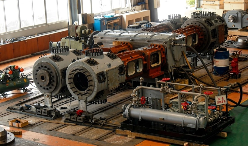
Factory acceptance test — every DW series unit undergoes a full mechanical run test at rated conditions including vibration measurement and ATEX safety system verification before shipment
Frequently Asked Questions — DW Series Gas Compressor
Request a Technical Proposal
Our engineering team has over 70 years of experience manufacturing large reciprocating gas compressors for coal gas networks, coke chemical plants, biogas facilities, and industrial gas pipeline stations across Russia and the CIS. The DW series gas compressor delivers API 618 opposed-balance performance with full GOST-R and Rostechnadzor documentation as standard — with spare parts dispatched from Russia without import delays and on-site service engineers available throughout Russia and CIS.
Discuss Your Gas Pipeline or Industrial Gas Compression Project
Process engineers with gas plant experience answer all enquiries. GOST-R and Rostechnadzor documentation included. Response within 48 hours.