Reciprocating Compressor Valve Failure: How Discharge Temperature Tells You Which Valve Is Failing

Practical Maintenance · Valve Failure · Discharge Temperature · Fault Detection · Gas Compressors

A rising discharge temperature is the earliest on-line warning of compressor valve deterioration — but the temperature alone does not tell you which valve is failing or whether the problem is a suction valve or a discharge valve. Read correctly, the pattern of temperature changes across the compressor stages and the profile of valve body temperatures on the cylinder head pinpoints the failing valve to within a single assembly, allowing targeted maintenance rather than a full cylinder teardown. This guide shows how to read the discharge temperature evidence, combine it with valve body temperature checks, and decide whether the compressor can continue running or needs immediate attention.

✓ Temperature Pattern Reading
✓ Suction vs Discharge Valve
✓ Run vs Shut Decision
✓ All Gas Services
compressor valve failure discharge temperature detection suction discharge valve ZW DW LW 4MW Russia

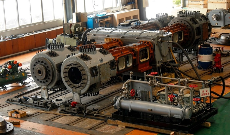
Reciprocating compressor undergoing acceptance test run — stage discharge temperatures, inter-stage pressures, and valve body surface temperatures are recorded at commissioning to establish the baseline against which all subsequent readings are compared. The difference between a temperature reading and its commissioning baseline is the primary tool for detecting valve deterioration before a failure occurs in service.

+3°C to +8°C
Early Warning
+20°C Sudden
Trip Immediately
Infrared Gun
Valve Body Check
Suction Hot
Suction Valve Fault
Discharge Hot
Discharge Valve Fault

Why Discharge Temperature Is the Universal Valve Condition Indicator

A gas valve in a reciprocating compressor that is leaking — whether suction or discharge — allows gas to flow in the wrong direction through the valve when it should be closed. This bypass flow converts compression work into heat without delivering useful gas output. The heat appears as an elevated temperature in the gas stream leaving that stage, measured at the stage discharge temperature sensor. Since the compressed gas carries the heat signature of every valve in the stage, the discharge temperature is the aggregate indicator of all valve condition in that stage — and a rise in discharge temperature above the commissioning baseline is the first measurable evidence that a valve is developing a leak.

The relationship between discharge temperature rise and valve leak severity is consistent enough across different gas services and compressor types to allow the following general rules to be applied at any ZW, DW, LW, or 4MW series installation:

Discharge Temperature Rise vs Action Required — All Gas Services
Rise Above Baseline Valve Condition Assessment Recommended Action
+3°C to +8°C Early seat wear; trace leakage beginning Monitor trend; plan inspection at next scheduled window
+8°C to +20°C Moderate leakage; 5–15% efficiency loss Schedule inspection within 500–1,000 h; reduce to standby if available
+20°C to +40°C Significant leakage; 15–30% efficiency loss Inspect within 200 h; switch to standby compressor if available
Sudden >+20°C Valve plate fracture or major seat damage Trip compressor immediately — do not restart before inspection

All rises measured against the commissioning baseline at the same suction conditions, discharge pressure, and cooling water temperature. Any sudden step change — regardless of magnitude — warrants immediate investigation regardless of absolute temperature.

Distinguishing Suction Valve Failure from Discharge Valve Failure
suction valve failure vs discharge valve failure temperature pattern infrared DW LW compressor Russia

The discharge temperature rise tells you that a valve in the stage is leaking — but it does not immediately identify whether the failing valve is a suction valve or a discharge valve. This distinction matters for two reasons: it determines the urgency of shutdown (discharge valve leakage is more severe at the same temperature rise) and it focuses the maintenance effort on the correct assembly. Two tools distinguish between the two failure modes:

Tool 1: Inter-Stage Pressure Trend

In a two-stage compressor, track the inter-stage pressure between stages at constant suction and final discharge conditions.

Rising inter-stage pressure → first-stage discharge valve leaking back into the cylinder, or second-stage suction valve leaking back from the inter-stage space. The first stage is working harder to push gas past the leaking valve, raising the inter-stage pressure above the design level.
Falling inter-stage pressure → first-stage suction valve leaking, reducing the mass flow the first stage delivers to the inter-stage space. Less gas at the same temperature produces lower inter-stage pressure.
Tool 2: Valve Body Temperature (Infrared)

Use an infrared thermometer or thermal imaging camera to measure the external surface temperature of each valve body cover on the cylinder head — both suction and discharge valves.

Hot suction valve body → gas leaking back through the suction valve dissipates energy as heat in the valve assembly. A suction valve body running 20–40°C above adjacent suction valves of the same stage is leaking.
Hot discharge valve body → gas leaking back through the discharge valve heats the discharge valve assembly. A discharge valve body running significantly hotter than adjacent discharge valves on the same stage has a leaking seat or cracked plate.

The Five-Minute On-Site Diagnosis Procedure

When a discharge temperature alarm triggers or a rising temperature trend is observed, the following five-minute procedure — requiring only an infrared thermometer and access to the stage pressure gauges — localises the fault to a specific valve assembly before any cylinder is opened:

1
Record all stage discharge temperatures and compare each against the commissioning baseline. Identify which stage shows the elevated temperature. If only one stage is elevated, the fault is in that stage; if multiple stages show elevation, the fault may be in a shared component (inter-stage cooler blockage, cooling water failure) rather than a specific valve.
2
Check the inter-stage pressure on the stage immediately preceding the elevated temperature stage. Rising inter-stage pressure points to a discharge valve failure in the preceding stage or a suction valve failure in the current stage. Falling inter-stage pressure points to a suction valve failure in the preceding stage.
3
Scan all valve body covers on the suspected stage with an infrared thermometer. Record the temperature of each valve cover (suction and discharge). Compare the readings across the stage — a valve cover running 15°C or more above the others in the same category (suction or discharge) identifies the specific failing valve assembly.
4
Determine whether the hot cover is a suction or discharge valve. On a DW or LW series cylinder, suction valve covers and discharge valve covers are typically in fixed positions on the cylinder head — the arrangement is documented in the operating manual. Suction valve covers are on the suction-pressure side of the cylinder head; discharge covers are on the high-pressure side. Mark the failing valve assembly for replacement and proceed to the run/shut decision.
5
Apply the run/shut decision table below. A compressor with a localised valve fault identified by this procedure can often continue running to a planned shutdown window rather than requiring an emergency stop, provided the temperature rise remains below the action threshold and the trend is stable rather than accelerating.

Run vs Shut Decision: A Practical Framework
compressor valve failure run shut decision framework discharge temperature valve body DW LW ZW Russia

The decision to keep a compressor running with a known valve fault — accepting the energy efficiency loss and the risk of further deterioration — versus shutting down immediately for repair, depends on four factors. Each factor increases or decreases the acceptable run time before valve replacement:

Factor Run Extended Shut Sooner
Temperature rise rate Stable, not accelerating Accelerating rise (valve deteriorating fast)
Gas service Nitrogen, argon, refrigerant Oxygen service — any discharge valve fault triggers immediate shutdown
Standby availability Standby compressor available No standby — any trip stops supply
Fault type Gradual seat leakage (slow onset) Sudden rise — plate fracture suspected
Spare valve set on-site Yes — plan repair within 200–500 h No — order parts before extending run

For oxygen service: any detected discharge valve fault requires immediate shutdown and inspection before restart, regardless of temperature rise magnitude. A discharge valve with a cracked plate in oxygen service can send metal fragments into the cylinder bore — the downstream consequences (bore scoring, piston damage) are more severe than the valve replacement itself. The discharge temperature rise threshold for action in oxygen service is therefore effectively zero for sudden-onset events.

Related Application · Plastics Manufacturing

Blow Air Pressure Curve as the ISBM Equivalent of Discharge Temperature Trending

In an injection stretch blow moulding (ISBM) machine, the equivalent of discharge temperature trending for the industrial gas compressor is the blow air pressure curve monitoring during the moulding cycle. The blow air pressure at the mould cavity rises, holds, and vents in a defined profile for each bottle size — and any check valve or blow air circuit valve that is leaking changes this profile measurably. A slower pressure rise indicates a leaking check valve upstream of the blow station; a faster pressure decline during the hold phase indicates a leaking blow valve or mould seal. In both the industrial compressor and the ISBM machine, the performance parameter that is easiest to monitor continuously — discharge temperature in one case, blow pressure curve in the other — is the earliest and most sensitive indicator of valve condition. The diagnostic logic is identical: establish a commissioning baseline, track the deviation, localise the fault using a secondary temperature or pressure measurement, and decide run-to-plan or immediate repair based on the trend and the gas service risk level.

Related equipment: One-step three-station ISBM machines for PET bottle production — with blow air circuit valves subject to the same leakage detection logic as reciprocating compressor gas valves.

ISBM Machine ›injectionstretchblowmolding.com

FAQ — Valve Failure Detection by Discharge Temperature

Q1: The discharge temperature has risen 12°C above baseline on stage 2 of a DW series nitrogen compressor. The inter-stage pressure is also slightly higher than baseline. Which valve do I inspect first?
A 12°C rise on stage 2 combined with higher-than-baseline inter-stage pressure points to a leaking first-stage discharge valve or a leaking second-stage suction valve — both of which cause gas to flow back from the inter-stage space, adding heat to the inter-stage and increasing its pressure. The infrared valve body check distinguishes between them: scan all first-stage discharge valve covers and all second-stage suction valve covers. The hottest cover identifies the failing assembly. In Russian DW series compressors, the first-stage discharge valves are typically on the top of the cylinder head (high-pressure side) and the second-stage suction valves are on the low-pressure side of the second-stage cylinder head — but verify the arrangement from the operating manual for the specific model before interpreting infrared readings. Start with the first-stage discharge valves as they are statistically more likely to fail first, as they have operated at the higher first-stage compression ratio for the longest time.
Q2: The discharge temperature has risen on all stages simultaneously — does this indicate multiple valve failures at the same time?
Simultaneous discharge temperature rise across all stages rarely indicates multiple concurrent valve failures — the probability of several valves deteriorating to a leaking state at the same time is low unless the compressor has just returned from a long shutdown without a proper restart inspection. The most likely causes of simultaneous multi-stage temperature rise are: reduced inter-stage cooling effectiveness from fouled coolers or reduced cooling water flow (the most common cause), elevated cooling water inlet temperature in summer, increased suction gas temperature or superheat, or a motor speed reduction that has changed the compression ratio at constant discharge pressure. Check the inter-stage cooler outlet gas temperatures first: if they are all higher than the commissioning baseline by a similar margin, the inter-stage coolers are underperforming and valve condition may be normal. If the cooler outlet temperatures are normal but all stage discharge temperatures are elevated, then the suction gas is hotter than at commissioning — check the suction temperature and the source gas conditions.
Q3: After replacing a valve assembly, the discharge temperature has not returned to the commissioning baseline. What else should be checked?
If the discharge temperature remains elevated after a valve replacement, one or more of the following is likely: a second valve in the same stage is also leaking and was not identified during the initial infrared scan — repeat the scan on all remaining valves in the stage; the new valve was not correctly assembled — check valve plate orientation, spring installation, and seating face contact (improper installation is the leading cause of premature new valve leakage); the piston rings in the same stage are also worn, contributing a ring leakage heat load that persists after the valve is fixed — this is identified by a persistent inter-stage pressure anomaly even after the valve replacement; or the inter-stage cooler for that stage is partially fouled, preventing the replacement valve’s effect from being fully visible in the discharge temperature. A systematic re-baseline of all parameters immediately after the valve replacement — recording all temperatures, pressures, and valve body temperatures — establishes the new reference point and makes any remaining faults visible against the post-repair baseline.
Spare Parts

Valve Replacement Sets — ZW, DW, LW, 4MW Series

Complete suction and discharge valve replacement sets for all stages of ZW, DW, LW, and 4MW series compressors — valve plates, seats, springs, lift limiters, and gaskets. Stocked in Russia for 24–72 hour dispatch. Specify compressor model, stage number, and gas service when ordering.