Technical Knowledge · Valve Maintenance · Fault Detection · Service Life · Gas Compressors
Gas valves are the most common cause of unplanned shutdown in reciprocating compressors across all gas services across all gas services — nitrogen, oxygen, argon, CO₂, NH₃, and hydrocarbon refrigerants. A valve failure forces a compressor trip, interrupts the supply of process gas to the consuming system, and — if undetected — can damage downstream components. Understanding the mechanisms by which compressor valves fail, the on-line indicators that signal impending failure, and the maintenance practices that extend valve service life is essential knowledge for operators of ZW, DW, LW, and 4MW series reciprocating compressors in Russia and the CIS.
✓ Valve Failure Mechanisms
✓ On-Line Detection
✓ 2,000–5,000 h Intervals
✓ All Gas Services
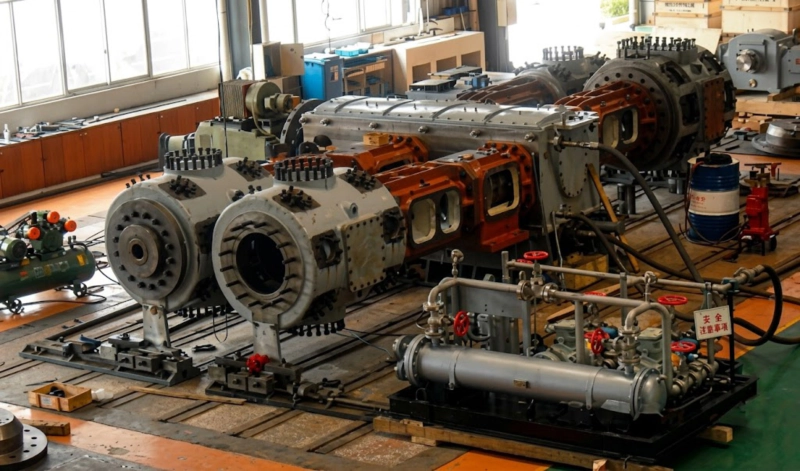
Reciprocating gas compressor undergoing acceptance test run — valve performance is verified at this stage by measuring suction and discharge pressures, inter-stage pressures, and discharge temperatures across each stage. These same measurements, tracked over the compressor service life, are the primary tools for detecting gas valve deterioration before a failure occurs in service.
How Plate Valves Work in Reciprocating Compressors
The ZW, DW, LW, and 4MW series reciprocating compressors all use plate-type gas valves — also called disc valves or ring valves — for both suction and discharge functions. The plate valve consists of a fixed seat with precision-lapped seating surfaces and ports, a thin steel valve plate that covers the ports when closed, a lift limiter that restricts the maximum valve plate travel, and a return spring that holds the plate against the seat when the valve is closed. Gas flow opens the valve by lifting the plate off the seat against the spring force; gas pressure reversal or spring force returns the plate to the seat, closing the valve.
In a reciprocating compressor, the valve plate opens and closes at every crankshaft revolution — typically 300–500 times per minute in DW and LW series compressors, and 200–350 times per minute in the larger, lower-speed 4MW frame. At 300 rpm and 8,000 operating hours per year, a valve plate impacts its seat or lift limiter approximately 144 million times per year of operation. Even small imperfections in plate flatness, seat surface finish, or spring rate uniformity multiply across this enormous number of opening and closing cycles to produce progressive wear and fatigue damage. The gas valve is therefore the highest-cycle-count component in the compressor and the component most likely to fail within the planned maintenance interval.
The Four Primary Valve Failure Modes
🚫
Failure Mode 1: Valve Plate Fracture
The valve plate fractures across one or more of the ports, producing fragments that block the port or are carried into the cylinder. Plate fracture is caused by: metal fatigue from repeated bending at the plate edge under gas load; impact fatigue from the plate striking the lift limiter at higher-than-design impact velocity; and stress concentration at manufacturing imperfections in the plate edge or port boundary. A fractured valve plate is the most serious failure mode because it can send metal fragments into the cylinder bore, causing piston, piston rod, or cylinder damage that turns a valve replacement into a major overhaul. Detection: sudden rise in discharge temperature of the affected stage; sharp rise in vibration at the compressor base; audible metallic knocking in the valve area.
⚠
Failure Mode 2: Seat Leakage (Blow-By)
The valve plate no longer seals tightly against the seat surface when closed, allowing gas to leak back through the valve from the high-pressure to the low-pressure side. Causes: progressive wear of the lapped seating surface by repeated impact; surface contamination from particulate in the gas stream depositing on the seating faces; scoring of the valve plate or seat by a hard particle passing through; and thermal distortion of the seat ring. Seat leakage is a gradual failure that worsens over time; it does not cause immediate compressor failure but reduces volumetric efficiency and increases discharge temperature progressively. Detection: slow rise in discharge temperature; falling compressor flow output; rising inter-stage pressure on the affected stage.
🔴
Failure Mode 3: Spring Fatigue and Breakage
The return spring that holds the valve plate against the seat when closed loses its preload gradually through metal fatigue — the cyclic loading of 300 million compressions per year progressively reduces the spring free length and spring rate. A spring with reduced preload allows the valve plate to open at a lower differential pressure than design, causing early valve opening and extended valve open time per cycle, which increases impact velocity at seat closure. A completely broken spring allows the valve to flutter randomly rather than opening and closing cleanly with each crankshaft revolution, producing variable compression and audible irregular valve noise. Detection: irregular valve noise; mildly elevated discharge temperature; verified by spring length measurement at inspection.
🔎
Failure Mode 4: Foreign Particle Impact
A hard particle — rust flake from upstream pipework, scale from the inter-stage cooler, weld spatter from a maintenance event, or particulate from the gas source — passes through the suction filter and strikes the valve plate or seat at high velocity. Even a single impact event can score the seating surface, dent the valve plate, or chip the seat rim, converting a previously sound valve to a leaking one instantaneously. This failure mode does not accumulate gradually — it can occur at any point in the valve service life and produces an immediate step-change in valve leakage. Prevention: maintain suction filter in good condition; flush upstream pipework before reconnecting after maintenance; inspect inter-stage cooler for scale and debris accumulation at each valve service.
On-Line Reciprocating Compressor Valve Condition Monitoring
The most practical on-line indicator of compressor valve condition is the stage discharge temperature, trended against the baseline measured at commissioning or at the previous valve service. A rising discharge temperature at constant operating conditions is the universal indicator of reduced volumetric efficiency from increasing valve leakage. The relationship between discharge temperature rise and valve condition follows a predictable pattern for seat leakage failures:
Discharge Temperature Rise vs Valve Condition — Typical Progression
| Discharge Temp Rise |
Valve Condition |
Recommended Action |
| +3°C to +8°C |
Early seat wear; minor leakage developing |
Monitor; plan inspection at next scheduled opportunity |
| +8°C to +20°C |
Moderate leakage; efficiency loss of 5–15% |
Schedule inspection within 500–1,000 hours; reduce to plan standby |
| +20°C to +40°C |
Significant leakage; efficiency loss of 15–30% |
Inspect within 200 hours; switch to standby compressor if available |
| Sudden rise >20°C |
Valve plate fracture or major seat damage |
Trip compressor immediately; do not restart before inspection |
Temperature rise measured relative to the commissioning baseline at the same operating pressure, flow rate, and cooling water temperature. Any sudden step change in discharge temperature — regardless of magnitude — warrants immediate investigation.
Additional on-line monitoring parameters that complement discharge temperature trending:
Inter-Stage Pressure Trending
A rising first-stage discharge pressure (inter-stage pressure) at constant suction conditions indicates increasing leakage past the first-stage discharge valve or through the first-stage suction valve. The direction of the pressure change depends on which valve is leaking and whether it is a suction or discharge valve failure. Tracking both the inter-stage pressure and discharge temperature together localises the failing valve to the specific stage and valve type.
Valve Body Temperature (External)
A leaking valve dissipates the energy of gas flowing back through it as heat in the valve body. An infrared thermometer or a thermocouple mounted on the valve body cap detects this elevated temperature as a local hot spot compared with adjacent sound valves. Comparing valve body temperatures across all valves of the same stage identifies the specific leaking valve without opening the cylinder.
Vibration Monitoring
Accelerometers mounted on the compressor cylinder head or valve body detect changes in the vibration signature at the valve impact frequencies. A valve plate that is cracked, poorly seated, or fluttering produces a different vibration spectrum from a sound valve. Vibration analysis is particularly effective at detecting valve plate fracture — the metallic impact of a fractured plate produces a distinctive high-frequency vibration component not present in the baseline spectrum.
Acoustic Emission
Acoustic emission sensors detect the high-frequency stress waves produced by crack propagation in the valve plate material. This technique provides the earliest possible warning of fatigue crack initiation in the valve plate — before the crack becomes a full fracture — and is used on critical compressor applications where valve plate fracture would cause unacceptable downstream damage (oxygen compressors, high-pressure gas cylinder filling stations).
Valve Service Life Extension: Practical Measures
Valve service life varies widely depending on operating conditions and maintenance practices. Under adverse conditions — wet gas with liquid carry-over, high discharge temperature, contaminated suction gas, or incorrect spring rates — valve life can be as short as 500–1,000 hours. Under good conditions with proper maintenance, the same valve design can achieve 5,000–8,000 hours before replacement is required. The following measures have the greatest practical impact on extending valve service life:
1
Control discharge temperature: The rate of valve plate fatigue crack growth increases with temperature. Keeping discharge temperatures below 140°C (for oxygen service) or below 160°C (for nitrogen, argon, and refrigerant service) significantly reduces the rate at which thermal cycling contributes to valve plate fatigue. The most effective temperature control measure is maintaining adequate cooling water flow and temperature through the inter-stage and aftercoolers; the second most effective is replacing worn piston rings promptly to prevent internal re-compression heat generation.
2
Maintain suction gas dryness: Liquid droplets entering the suction valve cause hydraulic hammer — a sudden pressure pulse when the incompressible liquid is trapped between the valve plate and the seat or lift limiter. A single hydraulic hammer event can break a sound valve plate instantly. Moisture separators with functioning automatic drains, regular inter-stage cooler drain valve checks, and suction gas monitoring for moisture content are essential for protecting valve integrity throughout the service interval.
3
Replace springs proactively: Valve springs are cheap compared to valve plates and cylinder components. Replacing all valve springs at every valve service — regardless of apparent condition — eliminates spring fatigue as a contributing cause of valve plate fracture and prevents the gradual performance degradation that accompanies reduced spring preload. The cost of a full spring replacement set is typically less than 5% of the total valve service cost including labour.
4
Keep suction filter maintained: The suction filter is the compressor’s primary protection against the foreign particle failure mode. A clogged or failed suction filter is worse than no filter — a clogged element can collapse and pass filter media into the valve along with the particles it was blocking. Inspect the suction filter element at each valve service and replace it if pressure differential across the filter exceeds the specified limit, if the element shows physical damage, or if the operating interval since the previous replacement exceeds the manufacturer’s recommendation for the gas cleanliness level.
Related Application · Plastics Manufacturing
Check Valves in ISBM Blow Air Systems: A Parallel Valve Failure Problem
Check valves in the high-pressure blow air circuits of injection stretch blow moulding (ISBM) machines experience a scaled-down version of the same plate valve failure mechanisms described in this guide. The check valves in the blow air manifold and in the inter-stage pipework of the ISBM blow air compressor open and close with every moulding cycle — at cycle rates of 1,200–2,000 cycles per hour on a high-speed ISBM machine. Over the compressor service life, these valves accumulate tens of millions of operating cycles and are subject to the same seat leakage, spring fatigue, and foreign particle failure modes as the industrial gas compressor valves described above. The maintenance principle is identical: monitor the blow air pressure curve for deviations from the commissioning baseline, inspect check valves at the scheduled interval, and replace springs proactively. The ISBM operator who understands reciprocating compressor valve failure is better equipped to anticipate and prevent the same failures in the machine’s own blow air system.
Related equipment: One-step three-station ISBM machines for PET bottle production — with high-pressure blow air check valves subject to the same plate valve failure mechanisms covered in this guide.
ISBM Machine ›injectionstretchblowmolding.com
FAQ — Compressor Valve Failure and Maintenance
Q1: How do I distinguish a suction valve failure from a discharge valve failure using temperature monitoring?
A leaking suction valve allows compressed gas to flow back from the cylinder into the suction line during the compression stroke — reducing the amount of fresh gas drawn in on the next suction stroke and therefore reducing the stage flow output. The effect on discharge temperature is moderate: the re-compressed gas arriving from the suction side adds heat, but the overall stage compression ratio at which the machine operates tends to decrease. A leaking discharge valve allows compressed gas to flow back from the discharge side into the cylinder during the suction stroke — the gas is then re-compressed from the same discharge pressure on the next compression stroke, adding the full work of re-compression as heat. The discharge temperature rise from a leaking discharge valve is typically larger than from a leaking suction valve of the same severity. Valve body temperature comparison is more direct: a hot suction valve body indicates a leaking suction valve; a hot discharge valve body indicates a leaking discharge valve. A systematic approach using both discharge temperature rise and valve body temperature measurement together identifies which specific valve is failing and whether it is suction or discharge.
Q2: Can a partially leaking valve be run to the next scheduled service, or should it be replaced immediately?
On a reciprocating compressor, a valve showing early-stage seat leakage — discharge temperature rise of 3–8°C above baseline — can generally be run to the next scheduled valve service provided: the discharge temperature remains well below the safety limit (140°C for oxygen, 160°C for other gases); the discharge temperature rise is stable rather than accelerating; flow output reduction is within acceptable limits for the process; and a standby compressor is available if the primary unit trips. A valve showing a discharge temperature rise above 20°C above baseline, or any evidence of valve plate fracture (sudden rise, audible metallic noise), should be taken out of service at the earliest opportunity — typically within 200 hours for the former and immediately for the latter. In facilities without a standby compressor, the threshold for planned interim maintenance is lower — the risk of unplanned shutdown must be weighed against the cost of an unscheduled valve service.
Q3: How should valve spare sets be managed for a remote site installation?
For reciprocating compressors at remote sites — Russian Far East fish processing plants, Arctic LNG facilities, or isolated industrial sites — the recommended spare valve inventory is a complete replacement set for every stage of the compressor, plus one complete additional set held in reserve. A complete stage valve set includes: suction valve assembly (seat, plate, spring, lift limiter, and all gaskets) and discharge valve assembly for that stage. Holding the reserve set on-site means that if the primary replacement set is installed during an emergency valve failure, the site is not left without spare valves while waiting for the next delivery. Valve spare sets should be stored in sealed, labelled packaging away from moisture and contamination; for oxygen service valves, sealed packaging with a desiccant is standard. Our Russian spare parts facility can provide complete valve sets for all ZW, DW, LW, and 4MW series stages within 24–72 hours for non-emergency orders, and same-day dispatch for emergency orders to major Russian ports and airports.
Spare Parts
Reciprocating Compressor Valve Spare Sets — ZW, DW, LW, 4MW Series
Complete valve sets for all reciprocating compressor stages — ZW, DW, LW, and 4MW series — suction and discharge valve assemblies, spring sets, gaskets. Stocked in Russia for 24–72 hour dispatch. Specify compressor model and series when ordering.