Technical Knowledge · Rod Packing · Seal Wear · Gas Leakage · Maintenance
Piston rod packing in a reciprocating compressor is the pressure seal that prevents process gas from escaping the compression cylinder along the reciprocating piston rod. In oil-free gas compressors, the piston rod packing is the boundary between the pressurised gas stream and the atmosphere — a worn or failed packing allows gas to escape, reducing compressor delivery, contaminating the environment, and in oxygen and ammonia service, creating a safety hazard. Understanding piston rod packing design, the causes and indicators of packing wear, and the correct replacement procedure is essential maintenance knowledge for ZW, DW, and LW series reciprocating compressor operators throughout Russia and the CIS.
✓ Packing Ring Design
✓ Wear Mechanisms
✓ 4,000–8,000 h Intervals
✓ O₂ / N₂ / NH₃ / CO₂
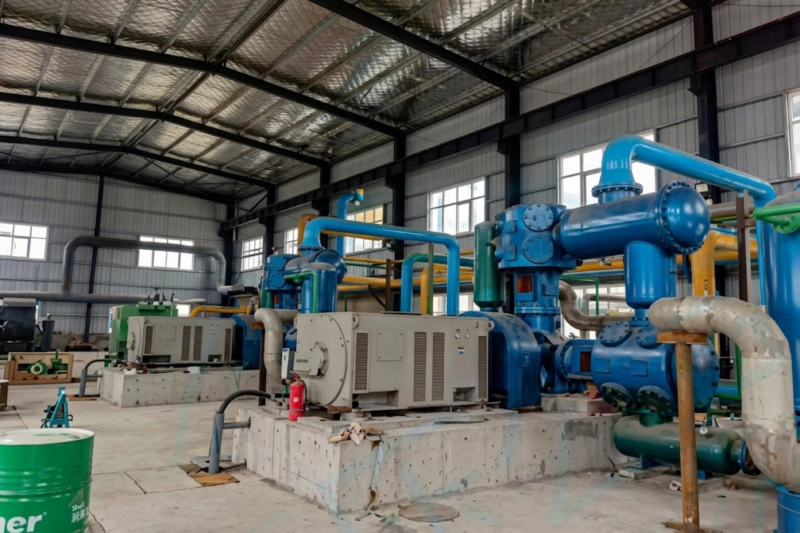
LW series reciprocating compressor in service — the piston rod packing gland is mounted at the cylinder end of the distance piece, visible as the flanged assembly where the piston rod exits the cylinder toward the crosshead. The packing rings inside this gland maintain the gas-tight seal at process pressure throughout the service interval. Packing ring condition is monitored by tracking gas leakage at the distance piece vent and measuring gas delivery against the commissioning baseline.
The Function of Piston Rod Packing in a Reciprocating Compressor
In every reciprocating compressor cylinder, the piston rod connects the piston inside the compression cylinder to the crosshead in the crankcase, passing through the cylinder wall as the piston moves back and forth. The rod must be free to slide axially with each stroke while preventing process gas from leaking out of the pressurised cylinder space along the rod-to-cylinder interface. The piston rod packing gland — an assembly of soft ring seals that press radially against the rod surface — provides this sealing function.
Unlike the piston ring, which seals between the piston and the cylinder bore in the radial direction while the piston moves axially, the piston rod packing must seal around a rod that reciprocates through the seal face with every crankshaft revolution. The sliding contact between the packing ring face and the moving rod surface generates friction and wear that progressively reduce the sealing effectiveness. Managing this wear rate — through ring material selection, rod surface finish maintenance, and operating condition control — is the central maintenance challenge for the rod packing throughout the compressor service life.
Packing Ring Design: Cut-and-Butt and Tangential-Cut Configurations

Piston rod packing rings cannot be installed as closed rings (like an O-ring) because the ring must pass over the piston rod end — which has threads, a piston attachment nut, or other obstructions that prevent a closed ring from being slid along the rod to its installation position in the packing gland. Packing rings are therefore split with a specific joint geometry that allows them to be assembled around the rod and then closed in the gland. Two joint designs are used in ZW, DW, and LW series packing:
Cut-and-Butt (Radial Cut)
The ring is cut radially with a straight cut perpendicular to the ring face. Two rings with offset cuts are used as a pair, assembled so that the cut of one ring is covered by the solid section of the adjacent ring — preventing a direct gas leakage path through the joint. The cut-and-butt pair is the simplest and most widely used packing configuration for lower-pressure stages (below 5 MPa) where the offset of two cuts provides adequate sealing without complex ring geometry. The cut allows the ring to be opened slightly for assembly over the rod and then spring-loaded closed against the rod surface in the gland.
Tangential-Cut (Stepped Cut)
The ring is cut at an angle to the radius (typically 45°), producing a stepped joint that interlocks when the ring is closed. The tangential cut provides a more tortuous leakage path through the joint than the straight radial cut, improving sealing effectiveness at higher pressures. Tangential-cut rings are used in the higher-pressure stages of multi-stage compressors — typically the second and third stages of DW and LW series machines — where the pressure differential across the packing is above 5 MPa and the more elaborate joint geometry is justified by the improved sealing it provides.
Ring Materials for Different Gas Services
| Gas Service |
Ring Material |
Typical Life |
Selection Reason |
| Oxygen (GOST 12.2.052) |
Virgin PTFE only |
4,000–6,000 h |
Carbon/graphite and bronze fillers prohibited per GOST 12.2.052. Virgin PTFE mandatory. |
| Nitrogen, argon (dry) |
PTFE + 25% carbon or glass |
5,000–8,000 h |
Filled PTFE gives better dimensional stability and lower wear rate than virgin PTFE in non-oxidising service. |
| CO₂ (food grade) |
Virgin PTFE or FDA-grade filled |
4,000–7,000 h |
Food-grade CO₂ requires filler materials approved for food-contact applications; standard carbon filler may not qualify. |
| NH₃ (ammonia refrigerant) |
PTFE + carbon or PTFE + bronze |
5,000–8,000 h |
Ammonia is compatible with both carbon-filled and bronze-filled PTFE. Bronze adds dimensional stability at NH₃ compression pressures. |
Service intervals assume good operating conditions: rod surface finish within specification, discharge temperature below design limit, no liquid carry-over events. Always specify the gas service when ordering replacement rod packing sets — using an incorrect ring material is a safety risk in oxygen service and a gas purity risk in nitrogen and CO₂ service.
Packing Wear Mechanisms and Failure Modes
1
Abrasive wear (primary mechanism): The packing ring face slides against the rod surface at every stroke — at 300 rpm, this is 300 contact cycles per minute, approximately 144 million cycles per year of continuous operation. Each cycle removes a small quantity of ring material from the sealing face. As the ring face wears, the contact geometry changes and the sealing pressure distribution shifts, reducing sealing effectiveness before the ring is fully consumed. Abrasive wear rate is proportional to contact pressure, sliding velocity, and the surface roughness of the rod. A rod with Ra above 0.4 μm causes abrasive wear rates 3–5 times higher than a rod at the specified Ra 0.2–0.4 μm.
2
Thermal degradation: High discharge temperatures accelerate PTFE creep and dimensional change in the packing rings. Rings at elevated temperature extrude into the clearance gaps of the gland box, losing the defined geometry that provides effective sealing. In oxygen service, elevated temperature accelerates the oxidation of the PTFE surface layer in direct contact with the gas, adding a chemical degradation component to the mechanical abrasion. Maintaining discharge temperature below 140°C (oxygen) or 160°C (nitrogen, CO₂, ammonia) extends packing life significantly.
3
Extrusion into ring joint gaps: Soft PTFE packing material flows under pressure into the joint gap between adjacent rings in the gland. Over time this extrusion creates a PTFE bridge across the joint that prevents the ring from following rod eccentricity, forcing it to ride on the rod at a fixed orientation. This leads to asymmetric wear — the ring wears faster on one side — and eventually to bypassing at the extruded joint. Rings showing significant joint extrusion are replaced even if the radial face wear is within limits.
4
Rod surface damage: Scoring, pitting, or corrosion of the piston rod surface in the packing contact zone creates a high-friction, abrasive interface that destroys packing rings rapidly and continuously. A single scored rod can consume a new packing set in 500–1,000 hours rather than 5,000–8,000 hours. Moisture carry-over from a failed inter-stage cooler drain is the most common cause of rod surface corrosion; particulate contamination is the most common cause of scoring.
On-Line Monitoring and Replacement Criteria
Packing condition is monitored in service through the middle cavity vent of the distance piece (described in blog-26). The vent gas flow rate and composition are the primary indicators of packing condition:
Low vent flow (baseline)
A small, steady vent flow with no visible gas jet or strong odour indicates packing in good condition. The baseline flow rate should be recorded at commissioning and after each packing replacement. Any sustained increase above baseline signals packing deterioration.
Rising vent flow rate
A vent flow rate 2–3 times the baseline indicates significant packing wear. The compressor can typically continue in service until the next scheduled maintenance window unless the flow rate continues to rise rapidly, suggesting accelerated wear from rod surface damage or high discharge temperature.
Strong gas odour at vent
For gas services with detectable odour (NH₃, CO₂ in concentration, some process gases), a strong gas smell at the distance piece vent indicates substantial packing bypass and should prompt inspection within 200–500 hours. For oxygen service, the vent is checked for oil with a wipe test; rising vent gas flow in oxygen service triggers investigation for packing wear.
Falling delivery rate
Gas leaking past worn packing reduces the compressor’s effective delivery. At a cylinder filling station, this manifests as increasing fill time per cylinder. At a process gas supply, it manifests as falling line pressure or reduced flow meter reading at constant operating conditions. A 5–10% delivery reduction relative to the post-replacement baseline warrants packing inspection at the next opportunity.
Related Application · Plastics Manufacturing
Rod Seals in ISBM Hydraulic and Pneumatic Actuators
Injection stretch blow moulding (ISBM) machines use hydraulic and pneumatic actuators throughout the mould clamping, preform transfer, and bottle ejection systems. Each actuator contains a rod seal — functionally analogous to the reciprocating compressor rod packing — that prevents hydraulic oil or pneumatic pressure from bypassing the piston along the actuator rod. The seal materials, wear mechanisms, and monitoring approach are direct parallels: PTFE or elastomer ring seals sliding against a hardened, polished rod surface; abrasive wear proportional to contact pressure and rod surface condition; leakage detection by observing oil weepage at the rod exit seal or by monitoring actuator cycle time extension (analogous to monitoring compressor delivery reduction). The maintenance principle is identical — inspect rod seals at scheduled intervals, check rod surface finish at each seal replacement, and replace proactively rather than running to failure. An ISBM technician who understands compressor rod packing wear has the conceptual framework to diagnose and maintain actuator rod seals systematically rather than reactively.
Related equipment: One-step three-station ISBM machines for PET bottle production — using hydraulic and pneumatic actuators with rod seals subject to the same wear mechanisms as compressor rod packing.
ISBM Machine ›injectionstretchblowmolding.com
FAQ — Piston Rod Packing in Reciprocating Compressors
Q1: What is the correct procedure for piston rod packing replacement?
Piston rod packing replacement in a reciprocating compressor follows this sequence: (1) depressurise the cylinder and distance piece completely — verify zero pressure with the stage pressure gauge before disassembly; (2) for oxygen service, degrease all tools and replacement parts with isopropyl alcohol before use; (3) remove the distance piece from the compressor frame to access the packing gland — note the orientation and stagger of the existing rings before removal as a reference; (4) remove worn rings and clean the gland cavity and ring grooves; (5) inspect the piston rod surface in the packing contact zone — measure surface roughness with a profilometer and check for scoring, pitting, and corrosion; (6) install new rings with the correct material for the gas service and the correct joint stagger (typically 120° between adjacent ring cuts for two-ring-per-groove designs); (7) reassemble the distance piece and torque the gland bolts to the OEM specification; (8) pressurise slowly with nitrogen to the operating pressure and verify vent flow is within the acceptable range before returning to gas service. For oxygen service, a nitrogen pressure test before reintroducing oxygen is mandatory.
Q2: Can piston rod packing be replaced without removing the piston from the cylinder?
On ZW, DW, and LW series reciprocating compressors, the piston rod packing gland is located at the cylinder end of the distance piece — not inside the cylinder itself. The packing gland can be removed and the packing rings replaced without removing the piston or disturbing the cylinder bore, piston rings, or gas valves. The distance piece is removed from the compressor frame as an assembly; the packing gland at its cylinder end is then disassembled to access the packing rings. The piston rod passes through the distance piece and remains attached to the piston in the cylinder throughout this process. This design allows packing replacement to be performed as an independent maintenance task without triggering a full cylinder disassembly — a significant time saving at planned maintenance shutdowns. The exception is when piston rod surface damage requires the rod to be removed for repair or replacement, which does require piston disassembly.
Q3: What piston rod packing spare sets should be held on-site for a remote installation?
For reciprocating compressors at remote installations — Far East fish processing, Arctic gas facilities, or isolated industrial sites — the minimum recommended on-site packing inventory is two complete replacement sets per stage of each compressor: one set for the next scheduled replacement and one set in reserve for an unscheduled replacement. A complete stage packing set includes: the correct number and type of packing rings per gland (cut-and-butt or tangential-cut as specified for that stage), the gland gaskets and O-rings, and any retaining springs or antiextrusion rings used in that stage’s gland design. Sets should be stored in sealed, labelled packaging — oxygen service sets in individually sealed bags away from hydrocarbons, non-oxygen sets in clean sealed storage. For sites more than 72 hours from the nearest spare parts stocking point, holding an additional reserve set is advisable. Our Russian spare parts facility stocks complete packing sets for ZW, DW, and LW series compressors for all gas services, available for same-day dispatch on emergency orders.
Spare Parts
Reciprocating Compressor Rod Packing Sets — ZW, DW, LW Series
Complete piston rod packing replacement sets for all stages of ZW, DW, and LW series compressors — virgin PTFE for oxygen service, carbon-filled and glass-filled PTFE for nitrogen and inert gas, food-grade PTFE for CO₂. Material certificates included. Stocked in Russia for same-day emergency dispatch. Specify compressor model, stage, and gas service.