The Forces a Reciprocating Compressor Generates
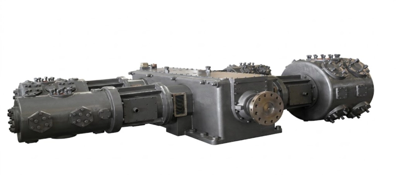
Every reciprocating compressor generates mechanical forces that are transmitted to the machine frame, the foundation, and the connected piping. These forces arise from two independent mechanisms: the inertia of the reciprocating masses (piston, piston rod, crosshead, and connecting rod) as they accelerate and decelerate through each stroke, and the gas pressure forces on the piston face as the gas is compressed and expanded. The gas pressure forces are transmitted through the cylinder, cylinder head, and frame to the foundation as static and dynamic loads that vary with the operating pressure. The inertia forces are the subject of the opposed-balance discussion: they are independent of the gas pressure and arise purely from the kinematics of the reciprocating motion.
The inertia force on a single-cylinder reciprocating mechanism can be decomposed into two harmonic components. The primary component oscillates at the rotational frequency of the crankshaft (one complete cycle per revolution). The secondary component oscillates at twice the rotational frequency (two cycles per revolution) and is smaller in magnitude — typically 20–30% of the primary — because it arises from the geometric approximation of the connecting rod motion rather than from the full reciprocating mass. Both components act along the axis of the cylinder — the horizontal direction for a horizontally-mounted cylinder in the DW and LW series.
For a single horizontal cylinder machine, the maximum primary horizontal force at the operating speed is:
Fᵍ = mᵣ × r × ω²
Fᵍ = Primary force (N)
mᵣ = Reciprocating mass (kg) — piston + rod + crosshead + fraction of connecting rod
r = Crank throw radius (m) — half the stroke
ω = Angular velocity (rad/s) = 2π × rpm/60
Example: DW series at 300 rpm, 80 kg reciprocating mass, 75 mm crank throw: Fᵍ = 80 × 0.075 × (2π × 300/60)² = 80 × 0.075 × 987 ≈ 5,900 N per cylinder. For a four-cylinder DW machine without cancellation this would be 23,600 N net horizontal force — enough to cause significant vibration problems in a rigidly-piped installation.
How the Opposed-Balance Frame Cancels Primary Forces
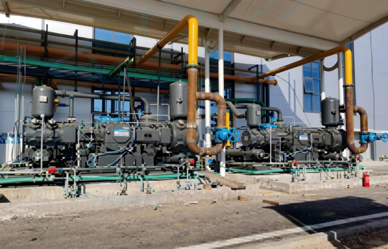
The opposed-balance frame achieves primary force cancellation through a geometric arrangement of the cylinders on the crankshaft. In the DW and LW series W-type frame, the cylinders are arranged in two opposed pairs: the cylinders on one side of the crankcase (Column A) are connected to crank throws that are 180 degrees from the crank throws of the opposite side cylinders (Column B). This means that when the pistons in Column A are moving toward the cylinder heads (compressing), the pistons in Column B are moving away from their cylinder heads (expanding), and vice versa. The inertia force generated by Column A pistons moving in one direction is exactly equal and opposite to the inertia force of Column B pistons moving in the opposite direction. They cancel.
More precisely: the primary inertia force vector of Column A at any instant in the crankshaft rotation is:
Column A primary force at angle θ:
Fᵃ = mᵣ × r × ω² × cos(θ)
Acting horizontally in the direction of piston travel, varying sinusoidally as the crank rotates.
Column B primary force at angle θ + 180°:
Fᵉ = mᵣ × r × ω² × cos(θ + 180°) = −Fᵃ
Exactly equal and opposite at every crank angle, provided the reciprocating masses in Column A and Column B are equal. This is a design requirement, not an approximation.
Net primary horizontal force on the frame:
Fᵃ + Fᵉ = Fᵃ − Fᵃ = 0
The net primary horizontal force transmitted to the foundation is zero at every crank angle. This is not a statistical average — it is exact cancellation at every instant of the operating cycle, provided the reciprocating masses are balanced.
What Is Not Cancelled: Secondary Forces and Rocking Couples
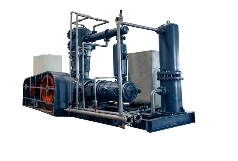
The opposed-balance frame cancels primary forces completely. It does not cancel secondary forces or the rocking couple. Understanding these residual dynamic loads is essential for foundation and piping design, because foundation specifications that ignore secondary forces will produce vibration problems even at a well-balanced DW or LW installation.
Secondary Forces — Acting at Twice the Operating Frequency
The secondary force arises from the geometric non-linearity of the connecting rod motion. A connecting rod of finite length does not cause the piston to follow a perfectly sinusoidal motion as the crank rotates — the piston spends slightly more time near top dead centre and slightly less near bottom dead centre than a perfect sine wave would predict. This deviation from sinusoidal motion produces a second harmonic component of the inertia force at twice the operating frequency. For a DW series machine at 300 rpm, the secondary force oscillates at 600 cycles per minute (10 Hz).
Unlike the primary force, the secondary force in an opposed-balance W-type frame does not cancel between the opposing cylinder columns. The reason is geometric: the secondary component of Column A’s piston motion and the secondary component of Column B’s piston motion are both at twice the operating frequency and in the same phase — they add rather than cancel. The net secondary horizontal force is approximately:
F₂ = mᵣ × r × ω² × (r/L) × 2
Where L is the connecting rod length and r/L is typically 0.20–0.30 for DW and LW series machines. The net secondary force is therefore approximately 40–60% of the single-cylinder primary force — a non-trivial residual load that the foundation must absorb. For the DW series example above: F₂ ≈ 0.5 × 5,900 N per cylinder × 4 cylinders ≈ 11,800 N acting at 10 Hz. This is the dominant vibration load that the foundation must be designed to resist.
Rocking Couple — Unique to the DW Frame (Not Present in 4MW)
The DW series W-type frame has two cylinder columns (Column A and Column B) separated by the crankcase width — typically 0.4–0.8 m between the centrelines of the two columns. The primary forces in Column A and Column B are equal and opposite (cancelled), but they act at different points along the crankshaft length. Two equal and opposite forces acting at different points along the same axis constitute a couple — a moment that tends to rotate the machine body about a vertical axis. This rocking couple oscillates at the operating frequency and its magnitude is:
M = Fᵃ × d
Where d is the distance between the centrelines of the two cylinder columns. For a DW series machine with d = 0.6 m and Fᵃ = 5,900 N per cylinder: M ≈ 5,900 × 0.6 = 3,540 N·m. This rocking couple is transmitted to the foundation as a moment load that requires the foundation to be wide enough in the perpendicular direction to resist the moment through normal foundation-to-ground friction and mass.
The 4MW series frame eliminates the rocking couple by using four cylinder columns in two opposed pairs symmetrically arranged around the crankcase. The moments from each opposed pair cancel the moments from the other opposed pair, producing zero net rocking couple in addition to zero primary force. This is the key dynamic balance advantage of the 4MW series over the DW series and the reason the 4MW designation is standard for Russian large-scale installations where minimum foundation vibration is required.
Foundation Design for DW and LW Series Compressors
Russian foundation design for reciprocating compressors is governed by GOST 25215 (Foundations for Reciprocating Machines) and SP 26.13330.2021 (the Russian building code for equipment foundations), which together specify the minimum foundation mass, the dynamic analysis requirements, and the permissible vibration amplitude at the foundation surface. The following design rules emerge from applying these standards to the DW and LW series force characteristics described above:
Rule 1: Foundation mass
The foundation mass must be at least 3 times the total operating weight of the compressor, motor, and baseplate assembly. For a typical DW series 110 kW machine weighing 4,500 kg assembled, the minimum foundation mass is 13,500 kg. GOST 25215 uses this mass ratio as a proxy for ensuring that the static and dynamic stiffness of the foundation is sufficient to keep vibration amplitudes at the machine mounting surface below 0.1 mm — the limit for acceptable operation of the compressor bearings and seals.
Rule 2: Foundation natural frequency
The foundation natural frequency in the horizontal direction must not be within 30% of the secondary force frequency (twice the operating frequency). For a DW series machine at 300 rpm, the secondary force frequency is 10 Hz. The foundation horizontal natural frequency must therefore be below 7 Hz or above 13 Hz. A foundation that resonates with the secondary force will amplify the 10 Hz vibration beyond the GOST 25215 amplitude limit even if the force magnitude itself is within acceptable bounds.
Rule 3: Rocking couple resistance
For a DW series machine, the foundation width perpendicular to the cylinder axis must be sufficient to resist the rocking couple through friction and mass. GOST 25215 requires a dynamic moment analysis for all compressors with rocking couples above a threshold magnitude. The DW series rocking couple at 300 rpm and typical reciprocating masses typically exceeds this threshold above 75 kW shaft power, requiring a formal dynamic analysis as part of the Rostechnadzor equipment installation documentation.
Rule 4: Anchor bolt specification
Foundation anchor bolts must be sized for the peak secondary horizontal force plus a wind load component where applicable. For an indoor installation the wind load is zero; for an outdoor or partially-exposed installation the wind load on the compressor body adds to the dynamic bolt load. The standard DW series foundation bolt pattern and diameter is specified in the machine installation drawing; the civil engineer must verify that the bolt embedment depth in the foundation concrete provides the required pull-out resistance for the dynamic load combination.
Impact on Piping Design and Instrument Placement

The residual secondary forces and rocking couple of a DW or LW series compressor affect the connected piping and instruments even though the primary forces are cancelled. The practical implications for the piping engineer and the instrument engineer are:
P
Piping natural frequency avoidance. The suction and discharge piping must be designed so that the natural frequencies of the pipe spans do not coincide with the secondary force frequency (10 Hz at 300 rpm) or the primary force frequency (5 Hz at 300 rpm, even though the net primary force is zero — the primary force does exist within each column and is transmitted to the cylinder nozzle). Standard pipe span length tables for gas compressor piping specify maximum unsupported span lengths for each pipe diameter and wall thickness to keep pipe natural frequencies above 15 Hz. Following these tables without modification for a DW or LW installation is acceptable but conservative; a finite element analysis of the specific piping layout allows longer spans where the geometry provides sufficient stiffness.
I
Instrument isolation from compressor vibration. Pressure transmitters, flow meters, and differential pressure instruments mounted directly on compressor nozzles or on unsupported pipe spans adjacent to the compressor will be subjected to the secondary force vibration and may produce noisy or erratic readings. The standard practice for Russian gas compressor installations is to mount precision instruments on separate instrument impulse lines with vibration-isolating tube bends — a minimum of two 90-degree bends in the impulse line between the process connection and the instrument body reduces vibration transmission to acceptable levels for most electronic pressure transmitters. Vortex flow meters and coriolis meters must not be mounted within the first two pipe span lengths of the compressor nozzles without a separate vibration analysis demonstrating that the vibration amplitude at the meter is below the meter manufacturer’s vibration sensitivity specification.
S
Suction pulsation and the acoustic resonance risk. Reciprocating compressors produce gas pressure pulsations in the suction and discharge piping at the operating frequency and harmonics. These pulsations are independent of the mechanical force balance — they exist even in a perfectly dynamically balanced machine. For the DW and LW series, the pulsation amplitude is governed by the API 618 or GOST standards for compressor pulsation control; a pulsation analysis is required for DW series machines above 75 kW and LW series machines above 110 kW. The interaction between pulsation-induced pipe vibration and the mechanical secondary force vibration is additive at frequencies where both coincide — the 10 Hz secondary force frequency can excite pipe spans at the same frequency as the fifth harmonic of a 60 rpm machine or the third harmonic of a 200 rpm machine, depending on the specific installation. A combined mechanical-acoustic analysis is required when the operating speed produces harmonics that fall within 10% of the mechanical secondary force frequency.
Related Application · Plastics Manufacturing
Blow Air Compressor Vibration and ISBM Machine Precision
The vibration engineering principles described in this guide for DW and LW series industrial gas compressors apply directly to the blow air compressor in an injection stretch blow moulding (ISBM) machine, though at a very different scale and installation context. The ISBM blow air compressor is a small reciprocating machine — typically 5–30 kW — that produces high-pressure air for the blowing station. At this small scale, the machine is typically mounted on an anti-vibration pad package rather than a dedicated concrete foundation, but the same principle applies: the reciprocating inertia forces must not be transmitted to the precision blowing station tooling or to the linear actuators of the stretch rod mechanism. An ISBM machine whose blow air compressor vibration is transmitted to the blowing station produces variable preform temperature distribution (because the stretch rod position is disturbed during the blowing stroke) and inconsistent blow air pressure distribution (because the pulsation from the compressor reaches the mould cavity). The opposed-balance compressor design — at whatever scale it is applied — reduces these vibration transmission effects. A reciprocating machine engineer who has designed foundations for DW series industrial compressors will immediately recognise the same force cancellation principles at work in the anti-vibration mount specification for an ISBM blow air compressor, even though the magnitudes are three orders of magnitude smaller.
Related equipment: One-step three-station ISBM machines for PET bottle production — with blow air compressor vibration isolation applying the same force balance principles described in this guide.
ISBM Machine ›injectionstretchblowmolding.com
FAQ — Opposed-Balance Compressor Forces and Installation
Q1: Our project requires mounting a DW series 110 kW compressor on a steel mezzanine structure rather than a concrete foundation. The structure engineer says the existing steel frame can support the static weight but has not analysed the dynamic loads. Is this acceptable?
No — the static weight check is necessary but not sufficient for a reciprocating compressor installation on a steel structure. The dynamic loads from the secondary forces (approximately 11,800 N at 10 Hz for a 110 kW DW machine) and the rocking couple (approximately 3,540 N·m at 5 Hz) must be added to the structural analysis. Steel structures are inherently more flexible than concrete foundations and have lower natural frequencies, which makes them more susceptible to resonance with the compressor’s dynamic forces. A steel mezzanine structure for a DW series compressor must be designed with the following requirements in addition to static weight capacity: the fundamental natural frequency of the structure in the horizontal direction of the cylinder axis must be outside the 7–13 Hz range to avoid resonance with the secondary force; the bolted connections between the compressor baseplate and the steel frame must be designed for the combined static weight plus peak dynamic load from secondary forces; and the structure must be stiffened to ensure that the vibration amplitude at the machine mounting surface does not exceed 0.1 mm under operating conditions. A formal dynamic structural analysis by a qualified structural engineer using finite element methods is required before a DW series compressor is installed on any steel structure in Russia. This requirement is not optional under GOST 25215 and Rostechnadzor equipment installation standards.
Q2: Why does the 4MW series have better dynamic balance than the DW series if both are described as opposed-balance machines?
Both the DW and 4MW series cancel primary forces through the opposed-balance arrangement, but the 4MW series additionally cancels the primary rocking couple that the DW series cannot eliminate. The reason lies in the geometry of the two frames. The DW series has two cylinder columns (one on each side of the crankcase), and the primary forces from these two columns cancel to give zero net horizontal primary force on the frame. However, the two columns are separated by the crankcase width — they do not act at the same point — so the equal and opposite forces constitute a couple that rotates the machine body. The 4MW series has four cylinder columns in two symmetrically-opposed pairs, arranged so that the rocking couple from one pair is equal and opposite to the rocking couple from the other pair. All primary forces cancel and all primary couples cancel, leaving only secondary forces as the residual dynamic load. For very large machines above 350 kW where the primary couple magnitude becomes significant, the additional capital cost of the 4MW series frame is justified by the substantially reduced foundation size and the ability to install the machine in locations where the DW rocking couple would require excessive foundation reinforcement. For machines below 350 kW at sites with conventional concrete foundations, the DW series primary couple is manageable within the GOST 25215 framework and the 4MW series’ additional balance is not typically required.
Q3: We are replacing an existing ZW series compressor with a DW series machine at the same location. The ZW was on an anti-vibration mount pad to reduce vibration transmitted to the process piping. Can we keep the anti-vibration mounts with the DW machine?
The anti-vibration mount pads that were appropriate for the ZW machine may not be appropriate for the DW series replacement. The ZW series L-type frame generates significant primary horizontal forces that the anti-vibration mounts must attenuate before they reach the piping. The mounts are therefore relatively soft in the horizontal direction — soft enough to reduce the ZW primary force transmission to an acceptable level. The DW opposed-balance frame generates near-zero primary horizontal forces but does generate the rocking couple described in this guide. A soft horizontal anti-vibration mount that allows the machine to rock under the couple moment may actually amplify the rocking motion rather than attenuate it, causing the machine to rock on its mounts at the operating frequency — visible as a rhythmic oscillation of the machine body — and potentially causing fatigue at rigid pipe connections to the compressor nozzles. The correct mount specification for a DW series machine is a rigid or semi-rigid mount that restrains the rocking motion while providing acceptable attenuation of the secondary horizontal forces. The mount supplier must be informed that the machine is an opposed-balance type (DW series) with the specific operating speed and frame dimensions, rather than specifying mounts based on the total machine weight and operating speed alone. Our engineering team provides the mount specification data for DW and LW series machines on request.
DW and LW Series Compressors
Opposed-Balance Reciprocating Compressors with Full Installation Engineering Support
DW series (55–350 kW) and LW series (110–500 kW) opposed-balance reciprocating compressors for Russian industrial gas installations — supplied with dynamic force data for foundation design, piping nozzle load data for pipe stress calculations, and pulsation study data for acoustic analysis. GOST 25215 foundation design data included with the compressor documentation package. Specify your gas service, operating pressure, and installation location for a complete engineering data package within 48 hours.