Technical Knowledge · Compressor Design · Frame Types · Vibration · Russia / CIS
The opposed-balance reciprocating compressor frame is the defining design feature that separates industrial-grade reciprocating compressors for permanent process plant installation from smaller general-purpose machines. By arranging pistons on opposite sides of the crankcase so that their inertia forces cancel, the opposed-balance design reduces the alternating force transmitted to the foundation to near zero — protecting the integrity of rigidly-piped gas systems throughout a 20–30 year plant life. This article explains the mechanics of how opposed-balance works, why it matters for permanently piped gas and refrigerant systems, and how it differs from L-type and symmetrically-balanced frame designs.
✓ Inertia Force Cancellation
✓ ZW / DW / LW / 4MW
✓ Foundation and Pipework
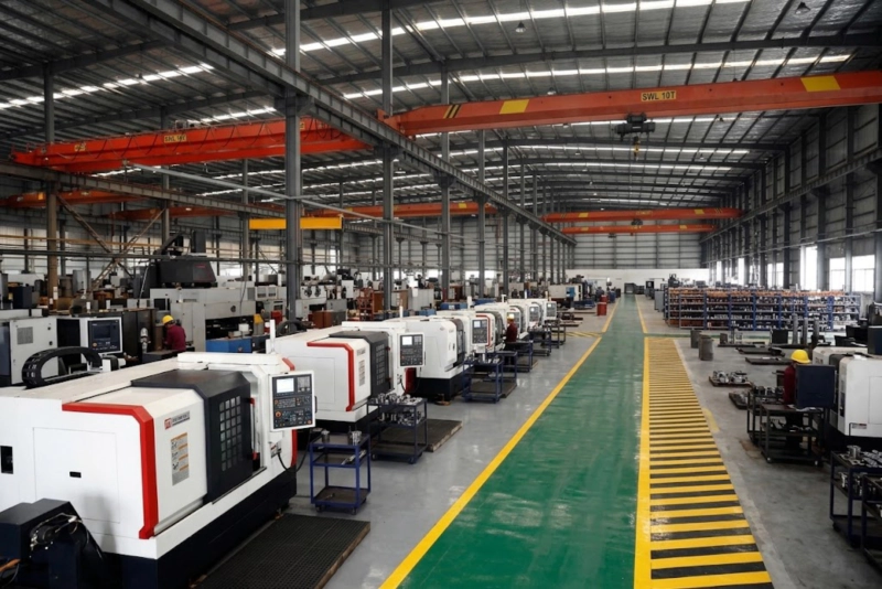
DW and LW series opposed-balance reciprocating compressors during machining — the symmetrical arrangement of cylinder columns on opposite sides of the crankcase is the geometric expression of the opposed-balance principle. Pistons on each side move in exactly opposite directions at every point in the crankshaft rotation cycle, cancelling the primary inertia forces that would otherwise be transmitted as an alternating force to the compressor foundation and connected pipework.
The Reciprocating Compressor Vibration Problem
Every reciprocating compressor converts rotary motion of the crankshaft into the back-and-forth (reciprocating) motion of the piston. A piston accelerating toward its cylinder head at top dead centre has significant momentum; as it decelerates and reverses direction, this momentum change produces a force that is transmitted through the connecting rod and crankshaft to the compressor frame and then to the foundation. This alternating inertia force oscillates at the crankshaft rotation frequency — and at twice that frequency for second-order forces — and is the fundamental source of reciprocating compressor vibration.
For a single-cylinder compressor with a piston mass of m and a crank radius of r rotating at angular velocity ω, the primary inertia force is approximately F = mrω² at the extremes of the piston stroke. At 300 rpm and a piston assembly mass of 10 kg with a 100 mm crank radius, this primary force is approximately F = 10 × 0.1 × (300×2π/60)² ≈ 9.9 kN — nearly a tonne of alternating force transmitted to the foundation at every crankshaft revolution. For a 110 kW compressor with larger piston assemblies and higher speeds, this force can reach 30–80 kN. This is the force that a single-cylinder or L-type compressor transmits to its foundation and to the pipework connected at its cylinder flanges.
How Opposed-Balance Cancels the Primary Force
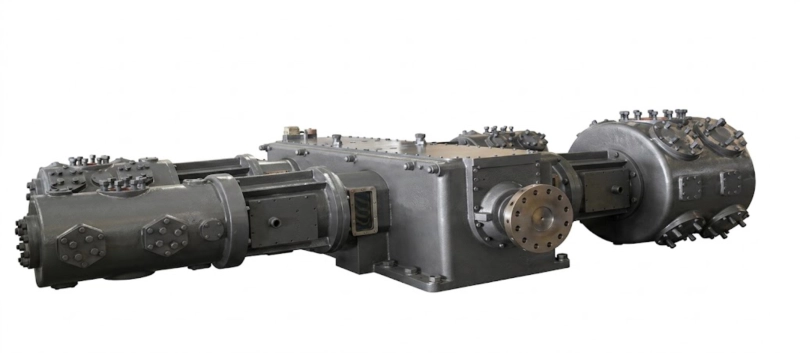
This arrangement solves the vibration problem by placing two identical cylinders on exactly opposite sides of the crankcase, with their pistons connected to the same crankpin so that they move in exactly opposite directions at every point in the rotation cycle. When the left-side piston is accelerating toward its top dead centre, the right-side piston is simultaneously accelerating toward its top dead centre in the opposite direction — generating an equal and opposite inertia force. The two forces cancel in the compressor frame, and the net force transmitted to the foundation is zero for primary inertia.
This is not an approximation or a partial reduction — it is exact cancellation of the primary first-order inertia forces, achieved by geometry rather than by counterweights or active compensation. The result is that an opposed-balance reciprocating compressor transmits no net primary alternating force to its foundation or to the pipework connected at its suction and discharge flanges, regardless of operating speed, pressure, or gas type. The only residual forces are secondary (second-order) inertia forces at twice the crankshaft frequency, and these are typically 5–15% of the primary force magnitude, small enough that they do not cause the progressive fatigue accumulation in pipework joints that primary forces would produce over a 20–30 year plant life.
The Three Frame Types: ZW, DW/LW, and 4MW
The Russian reciprocating compressor industry uses a naming convention that encodes the frame type directly in the series designation. Understanding this convention explains the mechanical properties of each series without requiring the mechanical drawings:
Why Pipework Fatigue Is the Key Engineering Reason
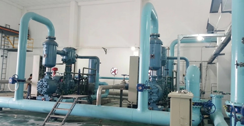
The practical engineering reason for specifying an opposed-balance or symmetrically-balanced compressor in a permanent process plant installation is not foundation cost or vibration sensation — it is the fatigue life of the pipework connected at the compressor flanges. When a compressor transmits an alternating force to its suction and discharge flanges, every weld in the connected rigid pipework experiences a small alternating stress at every crankshaft revolution. Each stress cycle accumulates damage in the metal at the weld toe according to the S-N fatigue curve for the material and weld geometry.
At 300 rpm and 8,000 operating hours per year, a compressor running for 25 years accumulates 360,000 hours of operation and approximately 6.5 billion crankshaft revolutions. Even a very small alternating stress at each revolution — produced by the secondary residual forces of an opposed-balance compressor — can approach the fatigue endurance limit of carbon steel butt welds over this time period. The full primary alternating force of an unbalanced L-type compressor at the same power level produces alternating stresses that are 10–20 times larger at every weld joint, reaching the fatigue damage accumulation threshold 10–20 times sooner. For a 25-year design life with no unexpected pipework weld failures, the primary force must be cancelled — which means an opposed-balance or symmetrically-balanced machine is not a preference but a design requirement for permanently rigidly-piped industrial installations above the power level where the L-type unbalanced force magnitude is significant.
Selecting the Right Reciprocating Compressor Frame
| Installation Type | Power | Pipework | Required Frame | Series |
|---|---|---|---|---|
| Small portable / flexible hose | 2–75 kW | Flexible hose | L-type acceptable | ZW |
| Permanent, rigidly piped, medium power | 55–350 kW | Rigid welded | Opposed-balance required | DW or LW |
| Permanent, rigidly piped, large power | 350–1,600 kW | Rigid welded | Symm. balanced required | 4MW |
| Cylinder filling, flexible manifold | 2–110 kW | Flexible hose | L-type acceptable | ZW |
The pipework connection type — flexible hose or rigid welded — is the primary determinant of frame type requirement, not the gas type or application. A rigidly-piped ZW installation above 75 kW is an engineering error regardless of how the application is described. Contact our engineering team if you are uncertain which frame type applies to your installation.
Why ISBM Blow Air Compressors Do Not Need Opposed-Balance Frames
The high-pressure blow air compressor of an injection stretch blow moulding (ISBM) machine operates at 35–40 bar and is connected to the blow moulding station by internal pipework within the machine frame — not by externally rigid-welded process pipework that extends across a plant. The compressor is part of the ISBM machine itself, and any vibration from the compressor is managed within the machine frame rather than being transmitted to an external gas distribution system. This is why the high-pressure air compressors built into ISBM machines do not require the opposed-balance or symmetrically-balanced frame specification that is mandatory for externally-piped industrial gas compressors: the vibration management is achieved by the machine structure rather than by geometric force cancellation in the compressor frame. The distinction illustrates the core principle — opposed-balance is specifically a requirement for permanent external pipework systems where weld fatigue accumulation over decades of operation is the design constraint.
FAQ — Opposed-Balance Reciprocating Compressor
DW, LW, and 4MW Opposed-Balance Compressors
All DW, LW, and 4MW series use the opposed-balance reciprocating compressor or symmetrically-balanced frames for permanent rigidly-piped industrial installation — nitrogen, oxygen, argon, CO₂, NH₃, and hydrocarbon refrigerant service. GOST-R certified with full Russian-language documentation.