Application Guide · Air Separation Plant · Nitrogen Product Compression · Russia / CIS
An air separation unit produces nitrogen, oxygen, and argon at low pressure. Delivering these gases to the consuming process — a pipeline network, a cylinder filling station, or an on-site industrial process — requires a product gas compressor matched to the ASU output pressure, the delivery pressure required, and the continuous duty demands of a permanent process plant installation. This guide covers how nitrogen compressors are specified for air separation plant service in Russia and the CIS.
✓ LW / DW / ZW Series
✓ Opposed-Balance Frame
✓ GOST-R Certified · Russia
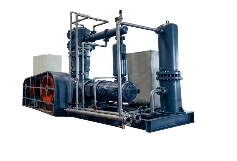
LW series opposed-balance nitrogen compressor for air separation plant product gas compression — suction from ASU column overhead at 0.02–0.15 MPa, discharge to pipeline or cylinder filling station at 1.0–30.0 MPa. Continuous 24/7 duty over 20–30 year plant design life. GOST-R certified.
The ASU Output Pressure Problem
A cryogenic air separation unit produces nitrogen at the top of the low-pressure column at near-atmospheric pressure — typically 0.02–0.15 MPa gauge depending on column operating pressure and altitude. This pressure is far below the delivery pressure required by any industrial consuming application: pipeline distribution networks typically operate at 0.5–4.0 MPa, nitrogen cylinder filling stations require 15–30 MPa, and high-pressure industrial processes may require 5–20 MPa. The product gas compressor bridges this pressure gap, taking the ASU product gas at near-atmospheric suction and delivering it to the consuming process at the required pressure in a continuous, uninterrupted flow that matches the ASU production rate.
The compressor at an air separation plant is therefore not simply a booster that raises an already-pressurised gas stream. It takes the low-pressure ASU product and performs the full pressure ratio from near-atmospheric to delivery pressure in one, two, three, or four stages depending on the delivery pressure required. At a typical nitrogen cylinder filling station fed directly from an air separation unit, the machine performs a pressure ratio of approximately 150:1 (from 0.1 MPa suction to 15 MPa discharge) across three compression stages. This is a significantly more demanding duty than boosting from a pressurised supply, and it defines the frame size, stage count, inter-stage cooling capacity, and power requirement of the machine selected for air separation plant service.
How ASU Output Pressure Determines Compressor Suction Design
The suction pressure of the nitrogen compressor at an air separation plant varies by ASU type and operating pressure:
0.02–0.05 MPa
0.05–0.15 MPa
Series Selection for Air Separation Plant Service
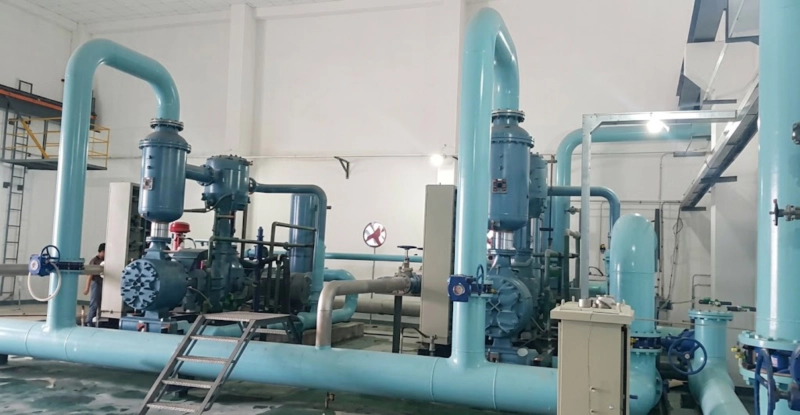
The nitrogen compressor at an air separation plant is a permanent installation: it is bolted to a concrete foundation, connected to the ASU product column overhead by rigid welded stainless or carbon steel pipework, and connected at its discharge to the plant pipeline header or cylinder filling manifold by equally rigid pipework. It runs 24 hours per day, 7 days per week, 330–350 days per year, for the design life of the air separation plant — typically 20–30 years. This permanent, continuously running, rigidly piped installation is the defining characteristic that governs series selection.
As established in the frame type selection guide, a permanently piped installation requires an opposed-balance frame to prevent progressive fatigue accumulation at pipework flange joints over the plant life. This eliminates the ZW series L-type frame from consideration for all but the smallest ASU nitrogen compressor applications (below 5–10 m³/h delivery flow) where the absolute force magnitude is low enough that L-type vibration does not produce unacceptable flange fatigue rates at the pipework connection points within the 20–30 year plant life.
| ASU Size | N₂ Output (Nm³/h) | Delivery Pressure | Recommended Series | Stage Count |
|---|---|---|---|---|
| Small ASU (on-site supply) | 10–50 | 1.0–4.0 MPa | ZW or DW | 2–3 stage |
| Small ASU + cylinder fill | 10–50 | 15.0–20.0 MPa | ZW or DW, 3-stage | 3 stage |
| Medium ASU | 50–200 | 1.0–15.0 MPa | DW or LW | 2–3 stage |
| Large ASU | 200–1,000 | 1.0–5.0 MPa | LW series | 2–3 stage |
| Large ASU + cylinder fill | 100–500 | 15.0–30.0 MPa | LW series, 3/4-stage | 3–4 stage |
N₂ output is at standard conditions (0°C, 0.101325 MPa). Actual flow at suction conditions depends on ASU column pressure, which determines first-stage cylinder volume requirement. Contact our engineering team with ASU specification documents for an accurate compressor sizing.
Oxygen Compression at the Air Separation Plant
Most air separation plants produce oxygen as well as nitrogen, and the oxygen product requires its own compression system. Oxygen compression at the air separation plant differs from nitrogen compression in one critical respect: the oil-free cylinder requirement. All oxygen compressors at pressures above 0.5 MPa must use oil-free PTFE or PEEK piston rings and double-compartment labyrinth distance pieces to prevent crankcase oil from migrating into the oxygen compression space, in compliance with GOST 12.2.052.
The DW and LW series oxygen compressors are available with the complete oil-free cylinder specification as standard for air separation plant service. In most Russian air separation plant installations, the nitrogen and oxygen product compressors are specified from the same DW or LW series family, with the nitrogen compressor using lubricated cylinders and the oxygen compressor using the oil-free PTFE cylinder variant. This approach simplifies spare parts stocking and maintenance training, since the two machines share the same crankcase, crankshaft, and connecting rod design despite the different cylinder configuration.
Continuous Duty Design Requirements
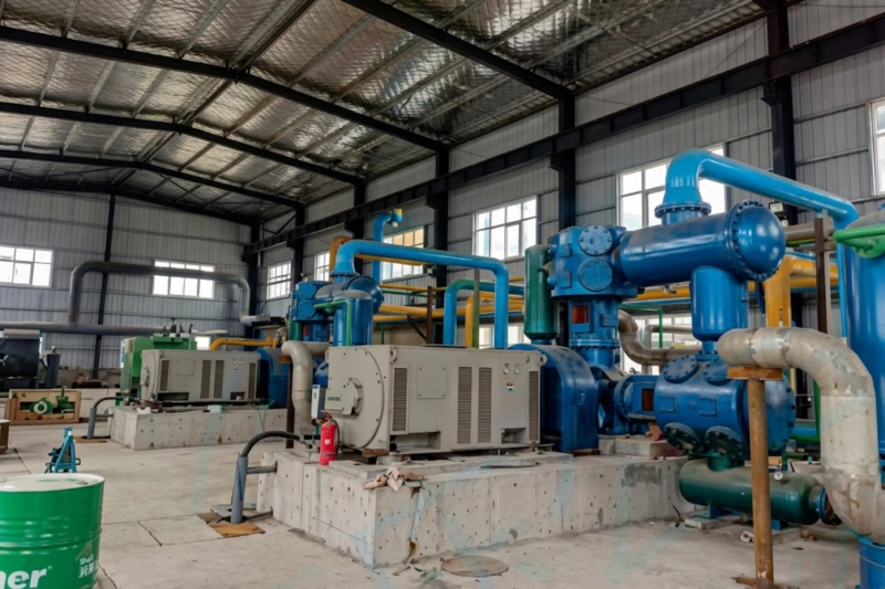
This machine is not a standby unit — it is a continuous-duty process machine that must run reliably without unplanned shutdown for extended periods between planned maintenance shutdowns. The ASU itself is a continuous-duty plant: if the nitrogen compressor trips, the ASU product must either be vented to atmosphere or the entire ASU is shutdown. Either outcome represents a significant production loss and, in the case of an ASU serving a continuous industrial process such as a steel plant or chemical facility, a potential production disruption at the consuming plant as well.
The continuous-duty design requirements for this nitrogen compressor go beyond the standard compressor specification:
On-Site Nitrogen Generation for ISBM Resin Blanketing
Large injection stretch blow moulding (ISBM) facilities consuming more than 500–1,000 Nm³/h of nitrogen for resin blanketing and mould atmosphere control sometimes evaluate on-site nitrogen generation via a small pressure-swing adsorption (PSA) or membrane nitrogen generator, rather than delivered liquid nitrogen or high-pressure cylinder supply. A PSA nitrogen generator producing 95–99.5% purity nitrogen at 0.5–0.8 MPa output can feed directly into the low-pressure nitrogen distribution network of a large ISBM facility without a booster compressor. If higher-purity nitrogen (above 99.9%) is required for food-contact or sensitive resin applications, the PSA generator is followed by a ZW series nitrogen compressor configured as a booster, taking the PSA output at 0.5–0.8 MPa suction and delivering nitrogen at 1.0–3.0 MPa to a buffer vessel, with a total compressor power of 11–37 kW — the smallest practical compressor application in continuous industrial service.
FAQ — Nitrogen Compressor for Air Separation Plant
Request an ASU Nitrogen Compressor Specification
DW and LW series compressors for air separation plant product gas compression — GOST-R certified, opposed-balance frame, lubricated N₂ and oil-free O₂ variants available from the same series. Russian-language documentation and local spare parts. Response within 48 hours.