Application Guide · Nitrogen Blanketing · Chemical Reactor · Inert Gas Systems · Russia
Nitrogen blanketing protects flammable and oxygen-sensitive chemical processes from ignition and oxidation by maintaining a continuous inert gas atmosphere above the liquid surface in reactors, storage tanks, and transfer vessels. The nitrogen blanketing compressor supplies and maintains this protective atmosphere against pressure fluctuations, consumption, and leakage. This guide covers the pressure and flow requirements, safety interlocks, and compressor specification for chemical reactor nitrogen blanketing systems in Russia and the CIS.
✓ 0.02–2.0 MPa Supply
✓ ZW / DW Series
✓ GOST-R Certified · Russia
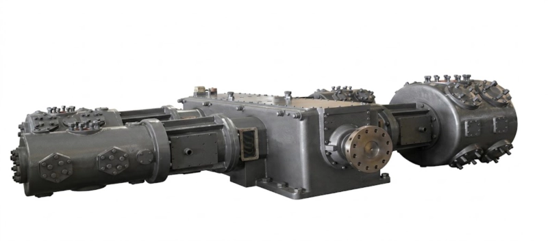
DW series nitrogen blanketing compressor for chemical reactor and storage vessel inert atmosphere service — opposed-balance frame, continuous duty, discharge pressure 0.5–5.0 MPa to the blanketing distribution header. The nitrogen blanketing compressor maintains reactor headspace pressure above the minimum blanketing setpoint against consumption, leakage, and vessel breathing during temperature and pressure fluctuations in the chemical process.
What Nitrogen Blanketing Does and Why It Requires a Compressor
Nitrogen blanketing — also called nitrogen padding or inert gas blanketing — is the practice of maintaining a continuous nitrogen atmosphere in the headspace of a vessel, reactor, or storage tank containing a flammable, oxidation-sensitive, or moisture-sensitive liquid or powder. The nitrogen atmosphere displaces air (and the oxygen it contains) from the headspace, eliminating the oxygen concentration required for ignition or oxidation reactions at the gas-liquid interface. For chemical reactors handling flammable solvents, oils, resins, or reactive intermediates, nitrogen blanketing is a primary layer of protection against fire and explosion in the reactor headspace and connected vent systems.
A static nitrogen charge in a closed vessel provides blanketing only as long as the vessel remains perfectly sealed and at constant temperature and pressure. In practice, vessels breathe: temperature changes during the process cycle cause the headspace gas to expand and contract, consuming nitrogen on cooling and venting on heating. Reactors connected to loading and unloading operations experience pressure fluctuations every time a valve opens or closes. Agitator shaft seals, manhole gaskets, and instrumentation connections all contribute a continuous small leakage rate. The nitrogen blanketing compressor compensates for all these losses by supplying a continuous flow of nitrogen to the blanketing header at a pressure above the minimum blanketing setpoint, controlled by a pressure regulator on each vessel that admits nitrogen when the headspace pressure falls below setpoint and closes when it reaches the upper limit.
For small vessels with low breathing rates and minimal leakage, a delivered liquid nitrogen supply or a bank of high-pressure nitrogen cylinders may be sufficient to maintain blanketing without a dedicated nitrogen blanketing compressor. For large chemical plants with multiple reactors, storage tanks, and transfer vessels connected to a continuous blanketing header — a configuration typical of Russian petrochemical, pharmaceutical, and specialty chemical facilities — a dedicated nitrogen compressor for blanketing drawing from a local nitrogen source (pipeline or on-site generator) is the standard and most economical specification.
Pressure Requirements for Chemical Reactor Blanketing
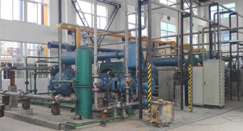
The blanketing pressure required at the reactor headspace is determined by the process design and safety case. For most chemical reactors at atmospheric or near-atmospheric operating pressure, the nitrogen blanketing setpoint is 0.02–0.05 MPa gauge — just enough above atmospheric to prevent air ingress through the vessel seals and any momentary negative pressure transients during the process cycle. However, the nitrogen blanketing compressor discharge pressure must be set significantly above the blanketing setpoint, to account for:
| Application | Vessel Pressure | Compressor Discharge | Stage Count |
|---|---|---|---|
| Atmospheric reactor blanketing | 0.02–0.05 MPa | 0.3–0.8 MPa | 1–2 stage |
| Storage tank blanketing | 0.01–0.03 MPa | 0.2–0.6 MPa | 1–2 stage |
| Pressurised reactor blanketing | 0.5–2.0 MPa | 1.0–3.0 MPa | 2–3 stage |
| Pipeline purging and padding | 0.1–0.5 MPa | 0.5–1.5 MPa | 1–2 stage |
| High-pressure autoclave blanketing | 2.0–5.0 MPa | 3.0–7.0 MPa | 2–3 stage |
Flow Sizing: Steady-State Blanketing vs Peak Purging Demand
The nitrogen compressor flow capacity for the blanketing system must cover two distinct demand modes: the steady-state blanketing flow that compensates for continuous leakage and vessel breathing, and the peak purging flow required during vessel entry, maintenance, and batch charging operations.
Steady-state blanketing flow for a reactor or storage vessel depends on the vessel volume, the temperature cycling amplitude during the process, and the aggregate seal leakage rate. For a typical 10 m³ atmospheric reactor operating through a 40°C temperature swing per batch cycle with moderate seal leakage, the steady-state nitrogen blanketing demand is approximately 1–3 Nm³/h. A chemical plant with 20 such reactors and associated storage vessels on a common blanketing header may have a total steady-state blanketing demand of 20–60 Nm³/h — a flow rate well within the ZW series range for atmospheric blanketing pressures, or the DW series for pressurised reactor blanketing above 1.0 MPa.
Peak purging demand is typically 5–20 times the steady-state blanketing flow, as the vessel must be swept with multiple vessel volumes of nitrogen to reduce oxygen concentration from ambient (21% O₂) to below 2% for safe entry. A buffer vessel in the blanketing system absorbs peak purging demand without requiring the compressor to be sized for the peak rate. With a properly sized buffer vessel, the nitrogen compressor can be sized for 1.3–1.5 times the steady-state demand, with the buffer vessel covering the difference during purging events that last 10–30 minutes.
Safety Interlocks for Nitrogen Blanketing Compressor Systems
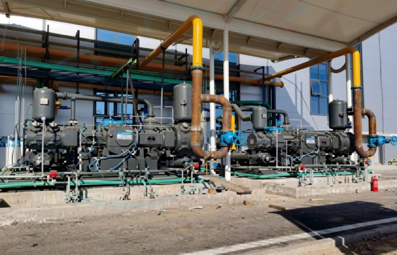
A nitrogen blanketing compressor at a chemical plant is part of the process safety system, not merely a utility machine. Its failure — either a compressor trip or an undetected loss of blanketing pressure downstream — can lead to air ingress into the protected vessel and potential ignition of flammable headspace vapours. For this reason, the nitrogen blanketing compressor control and interlock system must be specified as part of the process safety design, in compliance with GOST R 12.3.047 (explosion safety in chemical facilities) and the site-specific process hazard analysis (PHA) requirements.
Nitrogen Compressor Series Selection for Blanketing Service
The ZW and DW series nitrogen compressors cover the full range of chemical reactor nitrogen blanketing applications. Series selection follows the standard capacity and pressure criteria, with the additional consideration that nitrogen blanketing compressors at chemical plants are permanently piped installations where the opposed-balance frame advantage applies:
| Application | Flow (Nm³/h) | Discharge (MPa) | Series | Frame Note |
|---|---|---|---|---|
| Small plant, few reactors | 2–10 | 0.3–1.0 | ZW series | L-type acceptable at low flow |
| Medium plant, rigid piped header | 10–60 | 0.5–2.0 | DW series | Opposed-balance for permanent piping |
| Pressurised reactor blanketing | 5–40 | 1.5–5.0 | DW series | 2–3 stage; opposed-balance |
| Large petrochemical plant | 60–200+ | 0.5–3.0 | DW or LW series | LW for continuous large-volume |
Flow rates are design blanketing flow including standby margin. Actual compressor sizing must account for peak purging demand with buffer vessel. All series GOST-R certified with Russian-language documentation. Contact our engineering team for a blanketing system nitrogen compressor flow and pressure balance calculation.
Nitrogen Padding in PET Resin Handling — A Lower-Pressure Blanketing Application
The blanketing principle applied to chemical reactors has a direct parallel in the PET resin handling systems of injection stretch blow moulding (ISBM) facilities. PET resin is hygroscopic — it absorbs moisture from the atmosphere, which causes hydrolytic degradation during processing and produces hazy, brittle bottles with poor barrier properties. Large ISBM facilities handling more than 2–5 tonnes of PET per hour use nitrogen padding at the resin silo, hopper, and dryer inlet to maintain a low-humidity nitrogen atmosphere around the resin at all times. The nitrogen pressure for resin hopper padding is 0.005–0.02 MPa — near-atmospheric, and typically supplied directly from a low-pressure nitrogen generator without a compression stage. For larger silo systems requiring nitrogen at 0.05–0.2 MPa for pneumatic resin conveying under nitrogen, a small ZW series nitrogen compressor (2–8 kW) is the standard specification — the smallest practical continuous nitrogen blanketing compressor application in plastics manufacturing.
FAQ — Nitrogen Blanketing Compressor
Request a Nitrogen Compressor for Blanketing Service
ZW and DW series nitrogen compressors — GOST-R certified, opposed-balance frame — GOST-R certified, opposed-balance frame for permanent chemical plant installations, suction valve unloading capacity control, DCS integration. Russian-language documentation. Response within 48 hours.