Technical Knowledge · Multi-Stage Compression · Inter-Stage Cooling · Efficiency · Safety
Every multi-stage reciprocating compressor — whether compressing nitrogen nitrogen, oxygen, argon, CO₂, or refrigerant gas — incorporates inter-stage cooling between compression stages. In a reciprocating compressor, the coolers are not optional equipment added for operator comfort; they are fundamental to the thermodynamic efficiency and mechanical safety of the compressor. Removing inter-stage cooling or allowing it to operate at reduced effectiveness raises discharge temperatures, increases compression work, shortens valve and piston ring life, and — in oxygen service — creates a fire hazard. This article explains the engineering basis for inter-stage cooling and the practical consequences of cooler malfunction in Russian industrial gas compressor installations.
✓ Cooler Design Types
✓ Fouling and Maintenance
✓ All Gas Services
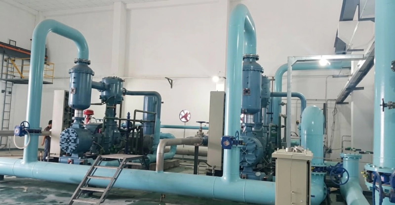
LW series multi-stage nitrogen compressor with inter-stage coolers visible between the cylinder stages — each cooler reduces the compressed gas temperature back to near-ambient before it enters the next compression stage, reducing the work of compression and keeping discharge temperatures within safe limits. Without inter-stage cooling, multi-stage compression approaching atmospheric-to-high-pressure ratios would produce discharge temperatures that destroy cylinder components and — in oxygen service — producing ignition conditions.
The Thermodynamic Basis: Why Cooling Between Stages Reduces Work
When gas is compressed without heat removal (adiabatic compression), its temperature rises as its pressure increases — the compression work appears entirely as internal energy of the gas, which manifests as elevated temperature. The work required to compress gas from pressure P₁ to pressure P₂ in an adiabatic process is greater than the work required for the same pressure ratio in an isothermal process (constant temperature). The ratio of adiabatic to isothermal compression work for nitrogen at a pressure ratio of 10:1 is approximately 1.25 — meaning adiabatic compression requires 25% more work than isothermal compression for the same outcome.
Isothermal compression — where the gas temperature is held constant throughout the compression process by continuous heat removal — is the theoretical minimum work ideal for compression. A perfectly cooled cooler that returns the gas to its suction temperature before the next stage begins approaches this isothermal ideal: the gas entering each stage is at the same temperature as it was at the first-stage suction, and the compression work in each stage is minimised. In practice, the inter-stage cooler cannot achieve perfect isothermal conditions — the gas leaves the cooler at approximately ambient temperature plus a 5–15°C temperature approach, which represents the practical limit of shell-and-tube water-cooled heat exchanger performance. This residual superheat above the isothermal ideal is the only thermodynamic inefficiency from inter-stage cooling; it is small and accepted as the engineering cost of a practical cooler design.
Quantifying the Inter-Stage Cooling Benefit
To make the efficiency benefit concrete, consider a three-stage nitrogen compressor compressing from 0.1 MPa to 15 MPa at a suction temperature of 20°C:
| Parameter | No Inter-Stage Cooling | With Inter-Stage Cooling |
|---|---|---|
| 1st stage suction temp | 20°C | 20°C |
| 1st stage discharge temp | 175°C | 175°C |
| 2nd stage suction temp | 175°C (no cooling) | 30°C (after cooler) |
| 2nd stage discharge temp | 350°C (destructive) | 182°C |
| 3rd stage discharge temp | ≫500°C (impossible) | 192°C |
| Power saving vs no cooling | Reference | ≈ 18–22% less power |
Temperatures are approximate for nitrogen (γ = 1.4) at equal pressure ratios per stage (~5.3:1 each). In practice, the uncooled scenario is mechanically impossible above Stage 2 — the table demonstrates why inter-stage cooling is not optional.
The table illustrates that inter-stage cooling is not merely an efficiency measure — it is a mechanical necessity. Without it, multi-stage compression to high pressures is physically impossible: the progressive temperature rise from uncooled stage-to-stage compression would reach temperatures that destroy every material used in compressor construction before the target discharge pressure is reached. Inter-stage cooling is therefore the enabling technology for all multi-stage industrial gas compression.
The Secondary Function: Moisture Knockout
As compressed gas cools in the inter-stage cooler, its relative humidity increases. If the gas contains moisture at the first-stage suction (as all atmospheric gas does, since even dry ambient air contains water vapour), the cooling process brings the gas toward and then past its dew point — at which point moisture condenses and must be separated from the gas before it enters the next compression stage.
Liquid water entering a compression cylinder causes hydraulic hammer — the same failure mechanism described for valve service life in blog-23. Because water is incompressible, a slug of liquid water trapped in the cylinder on the compression stroke cannot be compressed; the full gas pressure is applied to the liquid, which transmits it as a hydraulic impulse to the cylinder head, valve, and piston. A single hydraulic hammer event from liquid water carry-over can break a valve plate, crack a cylinder head, or bend a piston rod — converting a cooler maintenance oversight into a major compressor overhaul.
Every inter-stage cooler on the ZW, DW, LW, and 4MW series compressors includes an integral moisture separator with an automatic drain valve. The automatic drain opens periodically on a timer or on a float-actuated mechanism when the separator liquid level reaches the set point, discharging the condensate. The proper functioning of these automatic drains is one of the most critical — and most commonly overlooked — maintenance items on a multi-stage reciprocating compressor installation.
Inter-Stage Cooler Design: Shell-and-Tube Water-Cooled
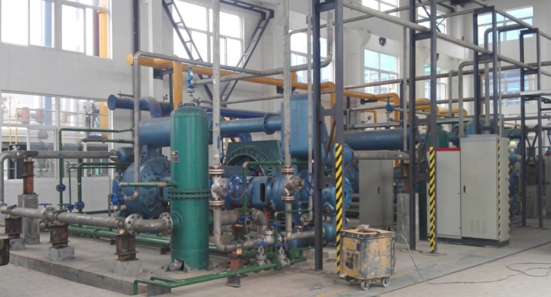
All ZW, DW, LW, and 4MW series reciprocating compressors use water-cooled shell-and-tube inter-stage coolers. The compressed gas passes through the tube side of the heat exchanger; cooling water circulates on the shell side. This arrangement keeps the cooling water separate from the gas and allows the heat exchanger to be cleaned on the water side without exposing the gas path to contamination.
Consequences of Inter-Stage Cooler Malfunction
Partial or complete loss of cooler effectiveness manifests progressively as the cooler fouls, scale builds up, or cooling water flow is reduced. The consequences develop in a predictable sequence:
Inter-Stage Cooling in ISBM Blow Air Compressors: The Same Principle
The high-pressure blow air reciprocating compressor of an injection stretch blow moulding (ISBM) machine compresses atmospheric air to 35–40 bar in three stages. Inter-stage coolers between each stage perform exactly the same thermodynamic function described in this article: returning the air to near-ambient temperature before the next stage begins, reducing the work of compression by 15–25% compared with uncooled multi-stage compression, and preventing the progressive temperature rise that would make three-stage compression to 40 bar physically impossible without cooling. The ISBM blow air inter-stage coolers are air-cooled (using a fan and ambient air rather than a cooling water circuit) because the heat loads are smaller and the machine is not connected to a site cooling water system. The same fouling, monitoring, and maintenance principles apply: if the ISBM inter-stage coolers are blocked or the cooling fans are faulty, blow air temperature rises, compression efficiency falls, and compressor component life is shortened.
FAQ — Inter-Stage Cooling in Reciprocating Compressors
Inter-Stage Cooler Performance: Reciprocating Compressor Service
All ZW, DW, LW, and 4MW series reciprocating compressors are supplied with water-cooled inter-stage coolers and automatic moisture separator drains. Replacement cooler elements, gasket sets, and drain valve assemblies are stocked in Russia for 24–72 hour dispatch. Contact our service team for performance trending support and cooler specification queries.