Engineering Guide · Cylinder Filling Station · Compressor Sizing · GOST 949 · Russia
Sizing a nitrogen compressor for a cylinder filling station involves more than matching a flow rate and a pressure to a product datasheet. The filling cycle dynamics, cylinder inventory, working pressure standard (GOST 949 or customer specification), and the distinction between average and peak flow determine the compressor capacity that delivers reliable throughput without oversizing. This guide walks through the sizing calculation step by step.
✓ ZW / DW / LW Series
✓ 3–Stage and 4–Stage
✓ GOST-R Certified · Russia
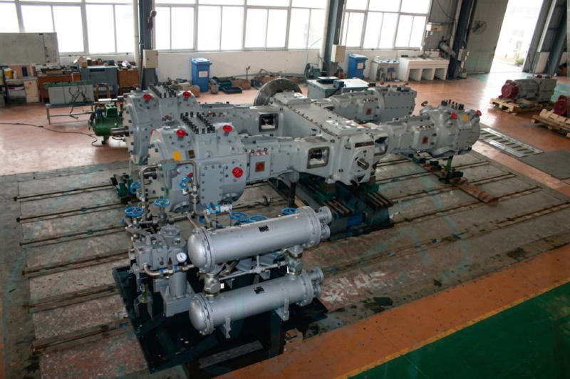
Reciprocating nitrogen compressor at a cylinder filling station — multi-stage opposed-balance configuration, discharge pressure to 15–30 MPa, GOST 949 filling standard. Correct compressor sizing requires accounting for filling cycle dynamics, cascade pressure matching, and peak vs. average demand — not just nameplate flow rate.
Step 1 — Establish the Required Filling Throughput
The starting point for nitrogen compressor sizing at a cylinder filling station is the required daily throughput — how many cylinders must be filled per shift or per day. This is a commercial requirement that comes from the gas distributor’s sales forecast or from the industrial facility’s consumption rate. The throughput figure must be specific: not just “50 cylinders per day” but “50 cylinders of 40-litre water capacity at 15 MPa filling pressure, filled in one 8-hour shift.”
Under GOST 949 — the Russian standard governing portable compressed gas cylinders — standard nitrogen cylinders have water capacities of 10, 20, 27, 40, and 50 litres, with a working pressure of 15 MPa (150 kgf/cm²). The most common sizes in Russian industrial gas distribution are 40-litre and 50-litre cylinders. The gas volume contained in each filled cylinder at 15 MPa can be calculated from the cylinder water capacity and the compressibility factor of nitrogen at filling conditions.
Vgas = 0.040 m³ × 15.0 / 1.027 = 0.584 m³ (Nm³) per cylinder
50-litre cylinder: 0.050 × 15.0 / 1.027 = 0.731 Nm³ per cylinder
Step 2 — Calculate the Required Compressor Flow Rate
Once the gas volume per cylinder is known, the required compressor flow rate follows from the throughput target and the available filling time. However, the compressor does not run at full flow for the entire shift — it must be sized for the peak demand period, not the average. In a cylinder filling station operating without a high-pressure buffer vessel, the compressor runs continuously during filling and is at full flow throughout each fill cycle. In a station with a buffer vessel cascade system, the compressor charges the buffer continuously and the cascade supplies the cylinders at a higher instantaneous flow than the compressor alone could sustain.
Qmin = 46.7 / (8 × 0.80) = 7.3 Nm³/h ≈ 7–8 m³/h at atmospheric suction
Add a 10–15% capacity margin to the minimum calculated flow to account for future throughput growth and to avoid running the nitrogen compressor at its absolute flow limit continuously. In this example the design flow becomes 8–9 m³/h — pointing to a ZW series nitrogen compressor in the 15–22 kW power range as the appropriate selection.
Step 3 — Determine the Discharge Pressure and Stage Count
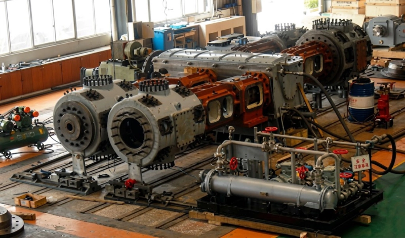
The discharge pressure of the nitrogen compressor at a cylinder filling station is determined by the cylinder filling standard and the cylinder working pressure:
| Cylinder Standard | Working Pressure | Required Compressor Discharge | Stage Count | Series |
|---|---|---|---|---|
| GOST 949 (Russia standard) | 15.0 MPa | 15.0–16.5 MPa | 3-stage | ZW / DW / LW |
| High-pressure N₂ storage | 20.0 MPa | 20.0–22.0 MPa | 3-stage | ZW / DW / LW |
| GOST 949 + cascade charge | 15.0 MPa | 20.0–25.0 MPa | 4-stage | ZW / LW |
| Export / international cylinders | 20.0–30.0 MPa | 20.0–30.0 MPa | 4-stage | ZW / LW |
Compressor discharge pressure is set 5–10% above cylinder working pressure to allow complete filling against rising back-pressure as the cylinder approaches full pressure. For cascade filling systems, the highest cascade bank must be charged to the full compressor discharge pressure.
The number of compression stages follows from the discharge pressure. Each stage compresses the nitrogen through a pressure ratio of approximately 3:1 to 4:1, with inter-stage cooling between stages to remove the heat of compression and maintain safe discharge temperatures. From atmospheric suction (0.1 MPa absolute):
Step 4 — Direct Fill vs Cascade System: Which Changes the Compressor Size
A direct-fill system connects the compressor discharge directly to the filling manifold. The compressor must supply gas to the cylinder against the cylinder back-pressure at every point in the fill cycle — from empty (residual pressure of 0.5–1.0 MPa in a previously used cylinder) to full (15 MPa). The instantaneous flow rate from the compressor equals its rated flow at the current back-pressure, which means the cylinder fill time depends on the compressor flow rate at the back-pressure corresponding to each filling stage. As the cylinder pressure approaches the compressor discharge pressure, the flow rate decreases and the final top-up becomes slow. For small stations filling a few cylinders per day, direct fill is the simplest and most reliable arrangement.
A cascade filling system uses a bank of high-pressure storage vessels charged by the nitrogen compressor between filling operations. When a cylinder is connected to the filling manifold, it is first equalised with the lowest-pressure cascade bank, then the medium bank, then the high bank, and finally topped up directly from the compressor if required. This sequential equalisation transfers gas from the cascade banks to the cylinder at a higher instantaneous flow rate than the compressor alone could sustain, reducing cylinder fill time significantly — particularly important for large-volume filling stations where cycle time per cylinder directly determines throughput. The cascade system allows a smaller nitrogen compressor to fill cylinders at a higher throughput rate than would be possible with direct fill, at the cost of the additional cascade vessels and associated pressure regulation equipment.
- Below 30–40 cylinders per shift
- Cylinders are large (50-litre) so cascade benefit is modest
- Space for cascade banks is limited
- Simplicity and low capital cost are priorities
- Nitrogen supply source is continuous (ASU product)
- Above 50 cylinders per shift
- Cylinders are small (10–20-litre) — cascade benefit is greatest
- Fill time per cylinder must be minimised
- Compressor must run smaller to reduce capital cost
- Demand is peaky rather than steady through the shift
Step 5 — Series and Frame Selection for the Calculated Parameters
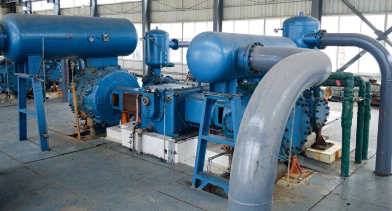
With the required flow rate and discharge pressure established, the nitrogen compressor series selection follows the same criteria discussed in the ZW vs DW vs LW selection guide: the ZW series L-type frame for small capacity (below 10–15 m³/h) and portable or semi-portable installations; the DW series opposed-balance frame for medium capacity (10–100 m³/h) in permanently piped stations; and the LW series opposed-balance frame for large-volume filling stations above 100 m³/h. For GOST 949 cylinder filling at 15 MPa, all three series are available in 3-stage configuration. For 30 MPa applications, ZW and LW series are available in 4-stage.
| Station throughput | Cylinders/shift (40-L) | Required flow (m³/h) | Approx. power (kW) | Recommended series |
|---|---|---|---|---|
| Small station | 20–40 | 2–4 | 11–22 | ZW series, 3-stage |
| Medium station | 60–100 | 6–10 | 30–55 | ZW or DW series, 3-stage |
| Large station | 150–300 | 15–30 | 75–160 | DW or LW series, 3-stage |
| High-volume station | 500+ | 50–100+ | 250–500+ | LW series, 3/4-stage (multiple units) |
Flow rates at atmospheric suction (0.1 MPa), 15 MPa discharge (GOST 949). Actual power depends on suction gas temperature, cooling water temperature, and specific machine model. Contact our engineering team for a sizing calculation specific to your station parameters.
Compressed Air Sizing for ISBM Blow Moulding — Same Calculation Logic
The cylinder filling sizing methodology — throughput per shift, gas volume per cycle, utilisation factor, peak vs. average demand — applies directly to sizing the blow air supply for an injection stretch blow moulding (ISBM) production line. In an ISBM facility, the blow air compressor must supply each mould station with high-pressure air (2.5–4.0 MPa) at a flow rate determined by the bottle volume, blow cycle time, and number of simultaneous blow stations. A three-station ISBM machine filling 1-litre PET bottles at a 6-second cycle time generates a peak blow air demand that must be covered by the compressor — typically 8–20 m³/h at 3.0–4.0 MPa — which falls in the same sizing range as a medium nitrogen cylinder filling station. Familiarity with the cylinder filling sizing logic transfers directly to blow air system specification.
FAQ — Nitrogen Compressor Sizing for Cylinder Filling
Get a Station Compressor Sizing Calculation
Send our engineering team your cylinder size, required throughput per shift, filling pressure standard, and whether you plan a direct-fill or cascade system. We will return a complete compressor sizing calculation and quotation within 48 hours.