Sizing Guide · Nitrogen Compressor · Cylinder Filling · 30 MPa · ZW DW Series · Russia
Sizing the nitrogen compressor for high-pressure cylinder filling is more involved than selecting a machine by nominal flow rate alone. The fill time per cylinder, the number of cylinders filled per shift, the cylinder volume and fill pressure, the suction source pressure, and the cascade or direct-fill strategy all interact to determine the required compressor flow rate. Get the sizing wrong in either direction and you either over-invest in compressor capacity or find that the station cannot meet shift production targets. This guide works through the sizing calculation from first principles for 30 MPa nitrogen cylinder filling and shows how to match the result to the ZW or DW series model designations.
✓ Stage Count
✓ Cascade vs Direct Fill
✓ ZW / DW Series Match
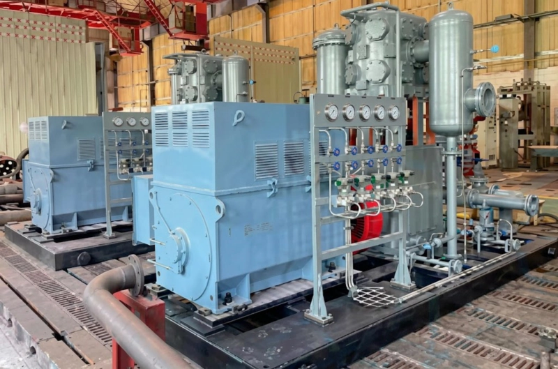
High-pressure compressor in nitrogen cylinder filling service — the ZW series covers 30 MPa discharge at flow rates from 0.15 m³/min to approximately 6 m³/min, sufficient for filling stations from a single cylinder bench to 50–80 cylinders per shift. The DW series extends coverage to higher flow rates for large industrial cylinder filling operations. Matching the correct model to the filling duty requires calculating the required average flow rate from the shift production target, accounting for the non-uniform flow demand of the filling cycle.
Step 1: Define the Filling Duty
The nitrogen compressor sizing calculation starts with the filling duty — the number and type of cylinders to be filled per shift. Three parameters define the duty completely:
Example duty for this guide: 40-litre cylinders (V = 40 L), fill pressure 30 MPa, 50 cylinders per 8-hour shift, initial pressure of incoming cylinders 1 MPa (cylinders returned partially filled). This represents a medium-scale industrial nitrogen filling station in Russia.
Step 2: Calculate the Required Compressor Flow Rate

The gas quantity required to fill one cylinder from the initial pressure to the fill pressure (at 20°C) is calculated from the ideal gas law. For a 40-litre cylinder filled from 1 MPa to 30 MPa:
Gas quantity per cylinder (standard conditions, 0.101 MPa, 20°C):
Qсыл = V × (Pᵅᵗᵗ − Pᵌᵗᵗ) / P₀ = 40 L × (30 − 1) MPa / 0.101 MPa ≈ 11,480 litres = 11.48 Nm³ per cylinder
Total gas per shift:
Qшифт = 50 cylinders × 11.48 Nm³ = 574 Nm³ per shift
Average flow rate required (8-hour shift, 85% utilisation factor):
Qавг = 574 Nm³ / (8 h × 60 min × 0.85) ≈ 1.41 Nm³/min = 1.41 m³/min at suction conditions
Model selection: ZW-1.5/300 or ZW-2/300 — the next standard model above the calculated flow requirement, providing a safety margin of approximately 6–40% above the calculated average demand.
The 85% utilisation factor accounts for cylinder connection time, purge time, and minor operational delays. A higher-throughput station with a practised filling team may achieve 90–92% utilisation; a lower-throughput or intermittent-use station should use 75–80%. The utilisation factor is the most significant source of uncertainty in the sizing — always verify against actual operating experience at similar stations before finalising the compressor selection.
Step 3: Stage Count for 30 MPa Discharge
Compressing nitrogen from atmospheric suction (0.101 MPa) to 30 MPa represents an overall pressure ratio of approximately 297:1. This ratio is far too large for a single compression stage — the discharge temperature would exceed 500°C and the volumetric efficiency would collapse to near zero. Multi-stage compression with inter-stage cooling divides this ratio across multiple stages, each operating at a practical 4:1 to 6:1 per stage.
| Stage Count | Per-Stage Ratio | Discharge Temp/Stage | Typical Pressure Range | ZW/DW Series |
|---|---|---|---|---|
| 2 stages | 17:1 | ≈ 320°C (too high) | Up to 1.5 MPa | Not for 30 MPa |
| 3 stages | 6.7:1 | ≈ 185°C | Up to 8–15 MPa | Borderline for 30 MPa |
| 4 stages | 4.1:1 | ≈ 120°C | Up to 30–35 MPa | Standard for 30 MPa |
| 5+ stages | Below 3.1:1 | Below 100°C | Above 30 MPa | Special ultra-high pressure |
A standard ZW or DW series compressor designated /300 (300 bar = 30 MPa) uses a 4-stage cylinder arrangement as standard. The model designation number after the slash (/300) directly specifies the discharge pressure; the stage count required to reach it is built into the machine design and does not need to be separately specified by the buyer.
Cascade vs Direct Fill: Which Strategy Requires a Smaller Compressor?

Two filling strategies are used at nitrogen cylinder filling stations — direct fill and cascade — and they have very different implications for compressor sizing:
The compressor fills the cylinders directly from its discharge, one manifold at a time. The compressor must supply the full flow rate required to meet the shift production target. As each cylinder fills to near the target pressure, the compressor discharge pressure rises with it — the compressor works against an increasing back-pressure throughout the fill cycle. This produces a declining flow rate as the cylinder pressure rises, requiring a larger compressor than the average flow calculation suggests to ensure the last part of the fill cycle does not become a bottleneck. Direct fill is used for small stations (5–20 cylinders per shift) or where the capital cost of storage banks is not justified.
The compressor charges a bank of high-pressure storage vessels (a cascade system) rather than filling cylinders directly. The storage bank is maintained at full pressure between filling sessions. When cylinders are connected for filling, gas flows from the highest-pressure storage bank first (by pressure equalisation), then from the next bank as pressure equalises, building the cylinder pressure step-by-step before the compressor tops up the storage bank at the end of the session. The compressor runs at a steady pressure against the storage bank rather than against a fluctuating cylinder manifold. A cascade system with a well-sized storage bank can be served by a compressor 30–50% smaller than a direct-fill station at the same shift throughput.
For our example duty of 50 cylinders per 8-hour shift at 30 MPa, the direct-fill approach requires a ZW-2/300 or ZW-3/300 (2–3 m³/min). The cascade approach with a 3-bank storage system of approximately 500 litres total at 30 MPa can serve the same duty with a smaller nitrogen compressor — ZW-1.5/300 (1.5 m³/min), which is smaller, less expensive, and consumes less energy per shift.
ISBM Blow Air Sizing: The Same Flow Rate Calculation Logic
Sizing the blow air compressor capacity for an injection stretch blow moulding (ISBM) machine follows exactly the same calculation logic as sizing a nitrogen cylinder filling compressor: total gas volume required per cycle multiplied by cycles per hour gives the required average flow rate, which is then matched to the available compressor capacity with an appropriate utilisation margin. For ISBM, the cycle parameters are the blow volume per cavity (determined by the bottle size), the number of cavities, and the machine cycle rate in bottles per hour. A one-step three-station ISBM machine producing 2-litre bottles at 1,200 bottles per hour requires approximately 0.8–1.2 Nm³/min of blow air at 35–40 bar — a duty that is sized and specified in exactly the same way as the nitrogen cylinder filling compressor in this guide. The engineering discipline of matching compressor capacity to cyclic production demand is identical across both applications.
FAQ — Nitrogen Compressor Sizing for 30 MPa Cylinder Filling
ZW and DW Series for 14.7, 20, and 30 MPa Nitrogen Filling
ZW series (2–75 kW, up to 30 MPa) and DW series (55–350 kW, up to 30 MPa) nitrogen compressors for cylinder filling stations — oil-free or lubricated cylinder options, cascade or direct-fill configuration, GOST-R certified. Send your duty specification for a sizing calculation and model recommendation within 48 hours.