Selection Guide · Nitrogen Compressor · PSA · ASU · DW Series · LW Series · Air Separation
The DW and LW nitrogen compressor series cover overlapping power ranges — both serve nitrogen pipeline supply at 55–350 kW shaft power — but they are not interchangeable for every air separation duty. The frame geometry, piston speed, valve design, and permitted gas service differ between the two series in ways that matter when the source is a PSA generator at 0.4–0.8 MPa suction versus a cryogenic ASU at near-atmospheric suction, when the pipeline pressure is 1 MPa versus 30 MPa, and when the nitrogen purity requirement is 99.5% versus 99.999%. This guide maps the duty characteristics of PSA and ASU nitrogen supply against the engineering properties of the DW and LW series, so that the series selection can be made on the engineering arguments rather than on price alone.
✓ DW vs LW Frame Differences
✓ Piston Speed and Valve Life
✓ Pressure and Purity Matrix
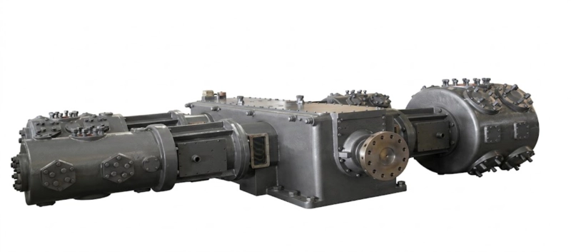
DW series opposed-balance reciprocating nitrogen compressors for PSA and ASU pipeline supply — the standard specification for 55–350 kW nitrogen compression duty in Russian industrial gas distribution, cylinder filling, and on-site pipeline supply. The LW series covers the same power range at a lower piston speed, extending valve and ring life for continuously-running ASU booster duties.
0.4–0.8 MPa
0.10–0.15 MPa
Higher Speed
Lower Speed
The Two Nitrogen Sources and What They Demand from the Compressor
Before comparing the DW and LW series, it is necessary to understand what PSA-sourced and ASU-sourced nitrogen demand from the downstream compressor in terms of suction pressure, gas quality, and flow variability. These three characteristics determine which series is the better fit, and getting them wrong leads to either oversized equipment or a compressor that fails prematurely on its ring and valve maintenance intervals.
A PSA nitrogen compressor application begins with the generator: produces nitrogen at 0.4–0.8 MPa outlet pressure and 95–99.999% purity depending on the adsorbent bed configuration and the cycle time. The flow from a PSA generator is inherently pulsed — the generator cycles between adsorption and regeneration phases on 30–120 second intervals, and during the regeneration phase of one bed the other bed is adsorbing, producing a gas flow that oscillates in pressure and flow rate by 5–15% around the mean value. A downstream surge vessel smooths the output, but residual pressure oscillation reaching the compressor suction is unavoidable unless the surge vessel is very large. The compressor suction valves must tolerate this moderate pulsation without accelerated fatigue.
An ASU (air separation unit) produces nitrogen as a cryogenic liquid or at near-atmospheric pressure (0.10–0.15 MPa) in gas phase from the distillation column. ASU nitrogen is extremely pure — 99.998–99.9998% N₂ — and extremely dry (dew point below −70°C), and the gas flow from the ASU column is exceptionally steady with pressure variation typically below 1%. A downstream nitrogen compressor taking suction from an ASU sees ideal suction conditions: steady pressure, no pulsation, ultra-low moisture, and no risk of oxygen carry-over. The compressor’s operating life in these conditions is close to the theoretical maximum for the ring and valve materials.
DW Series: Frame Design and Where It Excels
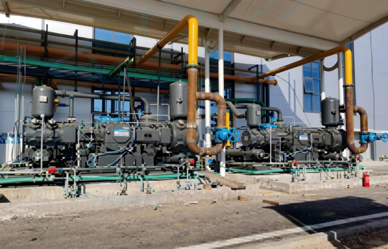
The DW series nitrogen compressor uses an opposed-balance W-type frame with cylinders mounted horizontally on both sides of the crankcase. At a given power rating, the DW frame runs at a higher piston speed than the LW frame — typically 2.8–3.5 m/s compared with 2.0–2.6 m/s for the LW at equivalent power. This higher piston speed allows the DW to use smaller cylinder bores for the same displacement, keeping the machine physically compact. The DW is the standard specification for PSA booster duty for several reasons:
LW Series: Frame Design and Where It Excels
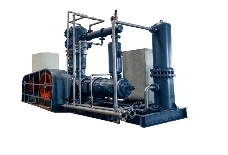
The LW series nitrogen compressor uses the same opposed-balance W-type frame geometry as the DW but with larger cylinder bores operating at lower piston speed. At equivalent power the LW cylinder bore diameter is 15–25% larger than the DW, and the piston speed is 20–30% lower. This design choice trades machine length for piston speed — the LW is physically longer than the DW at equal power, but the lower piston speed produces measurable benefits for continuous-running ASU compressor duties where cumulative wear over millions of cycles is the primary life-limiting factor:
Pressure, Purity, and Duty: The Selection Matrix
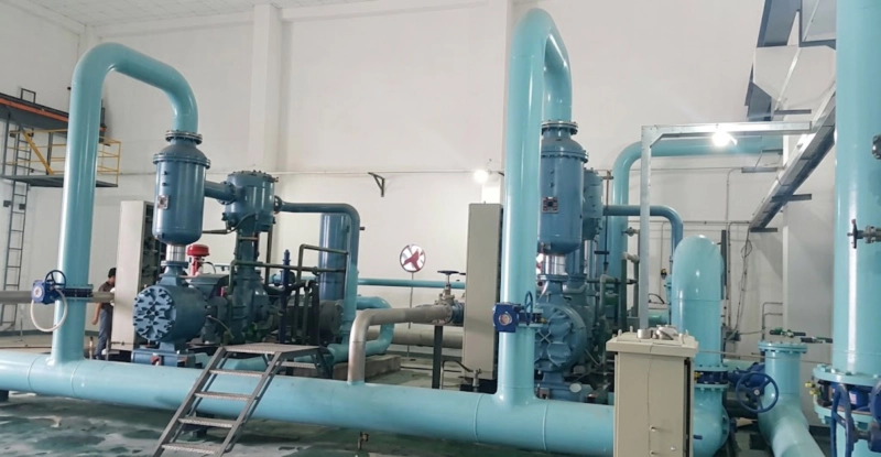
The following matrix summarises the DW versus LW selection recommendation across the most common air separation duty combinations encountered in Russian industrial gas and petrochemical applications. Each cell reflects the primary series recommendation and the key argument; where both series are viable the recommendation includes the tie-breaking factor:
| Duty Type | Source | Discharge Pressure | Series | Primary Reason |
|---|---|---|---|---|
| PSA booster — pipeline supply | PSA 0.4–0.8 MPa | 1–20 MPa | DW | Compact footprint; moderate per-stage ratio; good pulsation tolerance |
| PSA booster — cylinder filling | PSA 0.5–0.8 MPa | 30 MPa | DW | 4-stage 30 MPa standard configuration; low per-stage ratio from elevated suction |
| ASU N₂ booster — continuous pipeline | ASU 0.10–0.15 MPa | 1–15 MPa | LW | Lower piston speed extends ring and valve life for 8,000 h/year continuous duty |
| ASU N₂ — high-pressure cylinder filling | ASU 0.12 MPa | 30 MPa | LW or DW | Both viable; LW preferred for 24/7 filling plants; DW for shift-based intermittent duty |
| Small PSA — below 55 kW | PSA 0.4–0.6 MPa | 1–20 MPa | ZW | DW minimum power 55 kW; ZW covers 2–55 kW range for small PSA sources |
| Mixed PSA/ASU with standby | Either source | Any | DW (N+1) | N+1 standby with DW machines running at full capacity — LW life advantage does not apply when machines alternate on standby rotation |
Series recommendations are for the primary argument; both DW and LW are technically capable for all nitrogen service duties listed. The selection matrix identifies which series is the better engineering choice for the specific duty, not which is the only viable choice.
The Purity Question: Does the Compressor Affect Nitrogen Purity?
A question that arises frequently in PSA and ASU nitrogen compressor specification is whether the compressor itself affects the purity of the nitrogen delivered to the pipeline. The answer depends on the cylinder lubrication design and the compressor seal arrangement:
A lubricated DW or LW cylinder introduces trace quantities of compressor oil vapour into the nitrogen gas stream. At low oil carry-over rates (below 1 ppm by mass), this has no effect on nitrogen purity as measured by the N₂ percentage — but it does add hydrocarbon contamination that is unacceptable for food-contact nitrogen applications (MAP packaging, winemaking), electronics fabrication, and pharmaceutical nitrogen. For these applications, an oil-free cylinder design is mandatory regardless of whether the source is PSA or ASU.
An oil-free DW or LW cylinder with PTFE piston rings and PTFE rod packing introduces zero hydrocarbon contamination into the nitrogen stream. The purity of the delivered gas is determined entirely by the source — PSA purity with residual oxygen at 0.5–5 ppm to 0.5%, or ASU purity at 99.998–99.9998%. The oil-free cylinder design adds approximately 15–25% to the compressor capital cost and requires the PTFE ring and packing maintenance described in the dedicated piston ring guides, but is the correct specification for purity-critical nitrogen applications.
For standard industrial nitrogen applications — pipeline blanketing, purging, pipeline testing, and most cylinder filling for welding and industrial use — lubricated cylinders are acceptable and the lower capital and maintenance cost is preferred. The DW and LW series are offered in both lubricated and oil-free cylinder configurations; the gas service suffix in the model designation (-O for oxygen service, no suffix for standard nitrogen) indicates the cylinder type specified at manufacture.
Why ISBM Blow Air Purity Demands the Same Oil-Free Logic as PSA Nitrogen
The purity argument for oil-free cylinders in PSA nitrogen compression has a direct parallel in injection stretch blow moulding (ISBM) blow air systems. The blow air that contacts the interior of a PET bottle preform during the blowing cycle must be oil-free — any oil carry-over from a lubricated blow air compressor coats the interior of the bottle and creates a hydrocarbon contamination pathway for the food or beverage product the bottle will contain. Food safety regulations in Russia (TR CU 021/2011) and international markets prohibit lubricant carry-over in direct food-contact packaging applications. ISBM blow air compressors therefore use oil-free cylinder designs as standard — the same PTFE ring and packing design that distinguishes an oil-free DW nitrogen compressor from its lubricated equivalent. The selection logic is identical: lubricated cylinders for non-contact industrial duty, oil-free cylinders where the compressed gas contacts food, pharmaceuticals, or sensitive electronic components. The engineering discipline that governs PSA nitrogen cylinder selection for purity-critical applications is precisely the discipline that governs ISBM blow air compressor specification.
FAQ — DW vs LW for PSA/ASU Nitrogen Pipeline Supply
DW and LW Series Nitrogen Compressors for Air Separation Duty
DW series (55–350 kW) and LW series (110–500 kW) nitrogen compressors for PSA booster and ASU pipeline supply duty — lubricated and oil-free cylinder options, 1–30 MPa discharge pressure, GOST-R and EAC certified. Provide your nitrogen compressor duty specification — PSA or ASU source pressure, discharge pressure, required flow rate, and purity requirement for a series selection recommendation and model sizing within 48 hours.