Technical Knowledge · Capacity Control · Suction Valve Unloading · VFD · Energy Efficiency
Most industrial gas compressor installations do not operate at constant full capacity throughout their service life. Process demand varies with season, product mix, and facility utilisation — and the compressor must follow this demand without being shut down and restarted repeatedly. The two principal capacity control methods for reciprocating compressors are suction valve unloading (mechanical stepwise reduction) and variable frequency drive (continuous electrical speed control). Each has a different energy efficiency profile, capital cost, and suitability for different gas services and compressor types. Selecting the right capacity control method for a ZW, DW, LW, or 4MW series compressor has a direct and measurable impact on energy cost over the plant’s 20–30 year life.
✓ VFD Speed Control
✓ Energy Efficiency
✓ All Gas Services
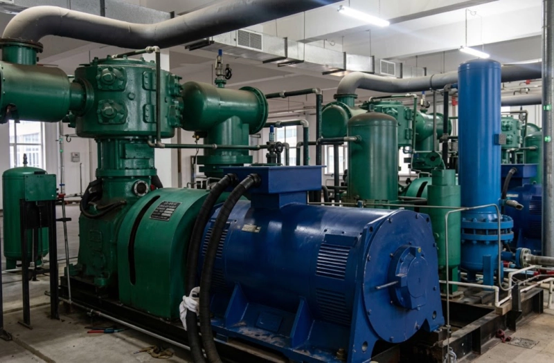
LW series reciprocating compressor in industrial service — capacity control allows the compressor to match its output to the actual process demand at any given time, avoiding the energy waste of running at full capacity when demand is lower. For reciprocating compressors in the DW, LW, and 4MW power range, suction valve unloading is the standard capacity control method in Russian industrial practice; VFD is an increasingly considered alternative for installations with highly variable demand and energy cost incentives.
Why Capacity Control Is Needed
A reciprocating compressor running at fixed speed and full load delivers a fixed mass flow at its design discharge pressure. If the process demand falls below this fixed delivery — during night shifts, seasonal low demand, or product changeover — the discharge pressure rises above the setpoint. Without capacity control, the only options are to shut the compressor down (losing the energy already in the system and incurring start/stop mechanical stresses) or to vent the surplus gas to atmosphere (wasting both the gas and the compression energy already invested in it). Neither option is acceptable for a continuously operating industrial gas system.
Capacity control allows the compressor to reduce its delivery proportionally to match actual demand, maintaining constant discharge pressure while consuming less energy than the full-load condition. The two dominant methods — suction valve unloading and VFD speed control — achieve this reduction by fundamentally different mechanisms and have different performance characteristics across the capacity range.
Suction Valve Unloading: How It Works
Suction valve unloading holds the suction valve of a cylinder open throughout the compression stroke, preventing gas from being trapped in the cylinder and compressed. When the suction valve is held open, the piston moves through its compression stroke but pushes gas back through the open suction valve rather than compressing it — the cylinder delivers no gas to the discharge system and consumes significantly less power than under loaded conditions. Pneumatically or electrically actuated «finger unloaders» push against the suction valve plate, preventing it from closing when the cylinder pressure rises above suction pressure.
On a multi-cylinder reciprocating compressor, individual cylinders or cylinder stages can be unloaded independently, giving stepwise capacity control in increments determined by the number and arrangement of cylinders. A typical DW series two-cylinder compressor provides three capacity steps: 100% (both cylinders loaded), 50% (one cylinder unloaded), and 0% (both unloaded, idling). A larger 4MW series machine with four cylinder columns can provide 25%, 50%, 75%, and 100% steps by unloading cylinders individually.
| Capacity Step | Cylinders Loaded | Typical Power Draw | Notes |
|---|---|---|---|
| 100% | All | 100% | Full load, design duty |
| 75% | 3 of 4 | 78–82% | Power does not reduce proportionally — unloaded cylinder still consumes friction and valve losses |
| 50% | 1 of 2 | 55–65% | At 50% capacity the compressor draws 55–65% of full-load power — the core inefficiency of unloading |
| 0% (idle) | None | 15–25% | All cylinders unloaded; motor runs at no-load speed. Used for warm standby rather than shutdown. |
Power percentages are indicative for a DW series two-stage compressor. Actual values depend on the specific machine design, the number of unloaded stages, and the compression ratio per stage.
Variable Frequency Drive: How It Works
A variable frequency drive (VFD) controls the speed of the electric motor driving the compressor by varying the frequency of the alternating current supplied to the motor. Lower motor speed directly reduces the piston speed and thus the volumetric flow delivered by the compressor. Because the compressor delivery is proportional to crankshaft speed (to a first approximation, ignoring the effect of speed on volumetric efficiency), a speed control provides continuously variable capacity output from its minimum speed to its maximum speed.
The energy efficiency advantage of VFD control over suction valve unloading is substantial at partial load. When a compressor with VFD runs at 70% speed to deliver 70% capacity, it draws approximately 70–75% of its full-load power — compared with 80–85% for a suction-valve-unloaded compressor at 75% capacity step. Over a full year of operation at 70% average load, this 10–15 percentage point power difference represents a meaningful energy cost saving, particularly for large compressors in the DW and 4MW power range where annual energy costs are significant.
Comparing the Two Methods: Efficiency, Cost, and Limitations
| Factor | Suction Valve Unloading | VFD Speed Control |
|---|---|---|
| Capacity range | Stepwise: 0, 50, 75, 100% | Continuous: 60–100% |
| Part-load efficiency | Moderate (non-linear) | Good (near-linear at 60–100%) |
| Capital cost addition | Low (unloader valves only) | High (VFD cabinet + harmonics filter) |
| Suitability for high-pressure O₂ | Standard | Requires careful valve dynamics review |
| Minimum speed limitation | None (step to 0% possible) | 60–70% of rated speed minimum |
| Maintenance complexity | Low (mechanical unloaders) | Higher (VFD electronics, cooling) |
| Warm standby | Excellent (idle at 15–25% power) | Possible but minimum speed applies |
| Russian industrial preference | Standard, widely used | Growing, energy-driven |
minimum speed limitation is the most practically significant constraint: a reciprocating compressor cannot run below approximately 60% of its rated speed because the lubrication oil pump flow and the dynamic bearing loads depend on crankshaft speed. Below 60% speed, bearing lubrication becomes marginal and valve dynamics change significantly from the design basis.
Which Method to Choose: A Practical Decision Guide
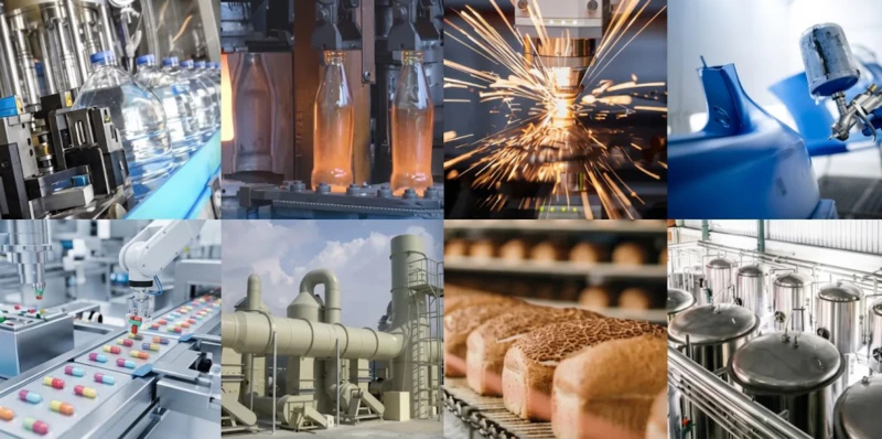
Capacity Control in ISBM: Why Variable Output Matters for PET Bottle Production
Injection stretch blow moulding (ISBM) machines for PET bottle production face a capacity control challenge that is structurally similar to the industrial gas compressor problem: the blow air compressor must supply high-pressure air at 35–40 bar to the blow station, but the air demand varies with the moulding cycle rate, the bottle size, and the number of cavities being used at any given time. Modern ISBM machines manage this through a combination of variable-speed blow air compressor control (analogous to VFD on the industrial compressor) and blow air pressure regulation, maintaining the correct blow air pressure profile at the bottle cavity regardless of the instantaneous cycle rate. The fundamental principle — matching compressor output to instantaneous demand rather than running at constant full capacity and wasting the surplus — is identical in both the industrial gas compressor room and the ISBM machine room. Efficient capacity control directly reduces the specific energy consumption per bottle produced, which is one of the key operating cost metrics for high-volume PET bottle manufacturing.
FAQ — Capacity Control for Reciprocating Compressors
Capacity Control Configuration for ZW, DW, LW, and 4MW Series
All ZW, DW, LW, and 4MW series compressors are available with suction valve unloading as standard. VFD configuration is available on request for DW, LW, and 4MW series machines in nitrogen, argon, CO₂, and refrigerant service. Our engineering team provides capacity control analysis and energy saving calculations for your specific operating load profile. GOST-R certified. Response within 48 hours.