Selection Guide · Argon Compressor · Air Separation · Opposed-Balance · DW Series · Russia
Argon recovery from air separation plants is technically demanding in a way that nitrogen or oxygen recovery is not. The argon content of air is only 0.93% by volume, and the recovery process must separate argon from both nitrogen and residual oxygen in the crude argon stream while preserving the ultra-high purity that welding, metallurgical, and specialty gas applications require. The compressor that handles argon between the distillation column and the product storage or distribution point is a critical component that must not introduce any contamination — no hydrocarbon from cylinder lubrication, no air from shaft seal leakage, and no reactive metal particles from wetted surfaces — while operating reliably enough to sustain the argon recovery output of the entire ASU. This guide covers the argon compressor selection from the DW series opposed-balance platform, the argon purity preservation requirements specific to argon service, and the integration considerations for Russian air separation plant retrofits and new ASU installations.
✓ Opposed-Balance Frame Advantages
✓ Purity Preservation
✓ Russian ASU Integration
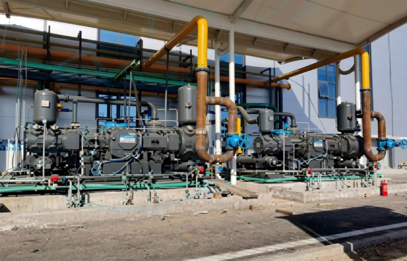
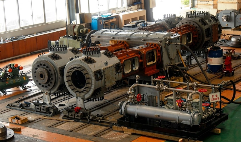
DW series opposed-balance reciprocating compressors at a Russian air separation facility — argon service places unique demands on the compressor that differ from both nitrogen and oxygen service. The argon product stream from the distillation column arrives at near-atmospheric pressure and must be compressed to cylinder filling pressure (14.7 MPa) or pipeline delivery pressure (0.5–5 MPa) without any contamination that would degrade the purity below the welding-grade or premium-grade specification. The DW opposed-balance frame provides the vibration performance required for rigidly-piped ASU installations, while the oil-free cylinder design eliminates the only contamination mechanism that cannot be removed by downstream purification.
of air
welding grade
mandatory
Balance DW
suction
Argon Recovery in Russian Air Separation Plants
Russian air separation plants (ASUs) producing industrial oxygen and nitrogen have historically focused argon recovery only at larger unit sizes above approximately 10,000 Nm³/h oxygen capacity. Below this threshold, the crude argon column is often present but the crude argon — a mixture of argon, residual nitrogen, and oxygen extracted from the oxygen column at the 99:1 argon-to-oxygen crossover point — is re-routed back into the oxygen column rather than being processed to product-grade argon. The reason is economic: the argon purification equipment (a deoxidiser reactor and a second distillation column to remove nitrogen) has a minimum viable scale below which the capital cost per tonne of argon recovered is too high relative to the market price of argon.
This economic threshold has been shifting downward over the past decade as Russian argon demand has grown with the expansion of welding, metal fabrication, and specialty chemical production. Russian ASU operators are now adding argon recovery to units as small as 6,000–7,000 Nm³/h oxygen capacity at sites where the argon product can be consumed internally or sold into the local cylinder market. Each of these argon recovery additions requires a new argon compressor to compress the product-grade argon from the distillation column exit pressure (near atmospheric, typically 1.05–1.15 bar absolute) to either cylinder filling pressure (150 kgf/cm² = 14.7 MPa) or liquid argon storage feed pressure (5–15 bar for a small liquefier). The DW series is the standard selection for these duties at the 55–350 kW shaft power range that matches the typical argon recovery compressor requirement at Russian medium-scale ASU installations.
The argon compressor at a Russian ASU is classified as a critical production asset because its availability directly determines the argon output of the entire plant. An argon compressor that is down for valve replacement or ring maintenance produces zero argon product, since the crude argon cannot be diverted to storage at the crude pressure — it must either be reprocessed or vented. The maintenance interval for valves and rings on the argon compressor is therefore a production-planning variable as much as a maintenance engineering variable, and the compressor specification must support the longest achievable maintenance intervals consistent with the purity requirements of the argon product.
Argon Service vs Nitrogen Service: The Key Differences in Compressor Specification
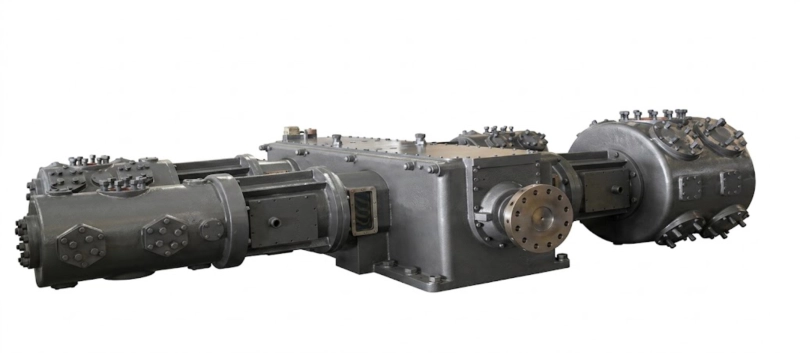
Argon and nitrogen share many physical properties — both are inert, monoatomic, non-toxic, and non-flammable — but the compressor specification for argon service differs from nitrogen service in four important ways that are not immediately obvious from the gas properties alone:
Argon has a ratio of specific heats (γ) of 1.67, compared with 1.40 for nitrogen. This higher γ means that adiabatic compression of argon produces a larger temperature rise per unit of pressure ratio than nitrogen compression at the same conditions. At a compression ratio of 4:1 — typical for one stage of an argon compressor — the theoretical adiabatic discharge temperature for argon is approximately 160–175°C compared with 140–155°C for nitrogen. This difference is significant because the cylinder lubrication oil degradation limit and the PTFE ring oxidation threshold both impose the same absolute temperature limits regardless of the gas being compressed — argon compression approaches these limits at lower compression ratios than nitrogen, requiring either more compression stages or more effective inter-stage cooling per stage than an equivalent nitrogen compressor.
Product-grade argon leaves the argon distillation column at 1.05–1.15 bar absolute — only marginally above atmospheric. The first-stage suction of the argon compressor is therefore near-atmospheric, and any pressure loss between the column exit and the compressor suction flange can result in the compressor taking suction at sub-atmospheric pressure. At sub-atmospheric suction, the crankshaft seal faces are critical: any inward leakage draws air into the argon circuit, introducing nitrogen and oxygen that contaminate the product and cannot be removed downstream without a full re-purification. The seal system on the first stage of an argon compressor at a Russian ASU must be designed specifically for sub-atmospheric operation — either a purge seal using low-pressure argon as the barrier gas or a mechanical seal designed for negative gauge pressure service.
Unlike nitrogen service where a lubricated compressor is acceptable for many industrial applications, argon product-grade service requires oil-free cylinder design without exception — regardless of the downstream purification equipment available. The reason is that argon cannot be purified of hydrocarbons by the same catalytic oxidation route used for nitrogen or oxygen purification, because argon does not react with the oxidation catalyst. Hydrocarbon carry-over from a lubricated argon compressor would require a dedicated activated carbon adsorption bed for removal, adding capital cost and a maintenance burden that a correctly specified oil-free machine eliminates completely. GOST 10157 (Russian standard for argon) specifies a maximum total hydrocarbon content that cannot be achieved with a lubricated compressor in the product supply chain.
Argon has a molecular weight of 39.95 g/mol compared with 28.01 g/mol for nitrogen. This higher molecular weight affects the valve plate dynamics: at the same piston speed and pressure differential, argon flows through a given valve port opening more slowly than nitrogen, requiring a larger valve opening (higher lift) to achieve the same volumetric flow. If valve plates designed for nitrogen service are used in argon service without review, the valve may not open fully during each cycle, reducing the effective valve flow area and increasing the pressure loss across the valve. The DW series argon compressor uses valve plates and lift limiters sized specifically for argon flow coefficients at each stage’s operating conditions, rather than carrying over the nitrogen valve geometry unchanged.
Why the Opposed-Balance DW Frame for Russian ASU Argon Duty
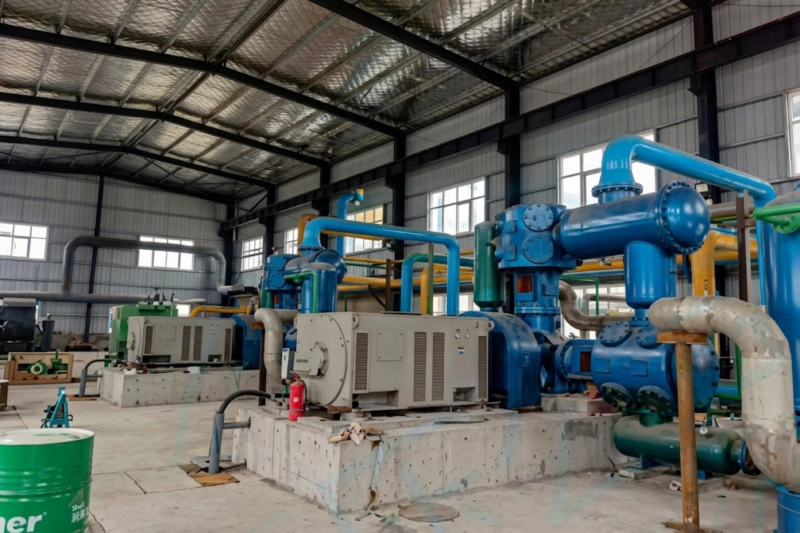
The DW series opposed-balance frame is the standard specification for argon compressors at Russian ASU installations above approximately 30 kW shaft power, and its selection is driven by the specific installation requirements of the ASU environment rather than by gas service alone. Three characteristics of the ASU installation environment make the opposed-balance frame the appropriate choice:
| Parameter | Nitrogen Service | Argon Service |
|---|---|---|
| Isentropic exponent (γ) | 1.40 | 1.67 (higher) |
| Discharge temp at 4:1 ratio | ≈ 142°C | ≈ 168°C (higher) |
| Cylinder lubrication | Optional (industrial grade) | Oil-free mandatory (all grades) |
| First-stage seal design | Standard labyrinth or PTFE | Purge seal or mechanical seal for sub-atm |
| Valve plate lift | Standard N₂ flow coefficient | Increased lift for Ar molecular weight |
| Inter-stage cooling duty | Standard | Enhanced (10–15% larger cooler area) |
| GOST standard | GOST R 51682 | GOST 10157 |
Purity Preservation Through the Compression System
GOST 10157 specifies argon purity grades for Russian industrial and specialty applications. The two most commercially significant grades are Grade 1 (99.993% argon minimum, oxygen below 5 ppm, moisture below 5 ppm, nitrogen below 50 ppm, total hydrocarbons below 0.1 ppm) used for welding and metal fabrication, and Grade 2 (99.99% minimum) for general industrial applications. The argon compressor must preserve the Grade 1 specification through the compression process without introducing contaminants at levels that approach or exceed these limits at any operating condition.
Three contamination pathways exist between the argon distillation column and the cylinder filling manifold that the compressor specification must address. Each pathway requires a specific engineering measure to prevent breakthrough to the product stream:
IN
IN
IN
Argon in ISBM Blow Air: Why Inert Atmosphere Matters for High-Clarity Pharmaceutical Bottles
While argon is not used as the primary blow air medium in standard injection stretch blow moulding (ISBM) production, it finds application in one high-value ISBM specialisation: the production of ultra-clear pharmaceutical PET bottles for lyophilised (freeze-dried) drug products and sensitive biologics where even trace oxygen exposure during the blowing process could compromise the container closure integrity assessment. In this application, a low-concentration argon purge in the blowing station — displacing oxygen from the environment immediately surrounding the preform during the blow and stretch phase — reduces the risk of trace oxidation at the bottle inner surface that would affect the oxygen transmission rate of the finished container. The argon used in this application comes from the same Russian ASU argon compressor circuit described in this article — GOST 10157 Grade 1 quality, compressed to pipeline delivery pressure, transported to the ISBM plant as cylinder gas or liquid argon. The argon purity that the air separation compressor preserves through oil-free operation and sub-atmospheric seal control directly affects whether the pharmaceutical ISBM application can be qualified under the relevant pharmacopoeial requirements. A Russian pharmaceutical packaging manufacturer who sources argon from a local ASU is therefore directly dependent on the argon compressor specification described in this guide.
FAQ — Argon Compressor for Air Separation Plants
ZW and DW Series Oil-Free Argon Compressors for Russian ASU
Oil-free ZW series (2–75 kW) and DW series (55–350 kW) argon compressors for Russian air separation plant argon recovery duty — virgin PTFE rings, argon-purge shaft seal for sub-atmospheric first-stage suction, enhanced inter-stage cooling for argon γ = 1.67, GOST 10157 compliance documentation. Provide your argon flow rate, suction pressure, cylinder filling or pipeline delivery pressure, and current ASU oxygen capacity for a model selection and integration specification within 48 hours.