What Nitrogen Blanketing Does and Why the Compressor Is a Safety-Critical Component
Nitrogen blanketing maintains a positive pressure of inert gas above the liquid surface or in the vapour space of a chemical reactor, storage vessel, or process vessel. The nitrogen blanket serves two simultaneous protective functions: it prevents ambient air from contacting the vessel contents (protecting against oxygen-initiated oxidation or flammable atmosphere formation), and it suppresses evaporation and vapour pressure buildup that would occur if the vapour space were at atmospheric pressure with no controlled inert gas blanket. In Russian chemical plants, nitrogen blanketing is applied to reactors handling oxygen-sensitive intermediates (organolithium compounds, Grignard reagents, alkoxides), flammable solvents with low flash points (diethyl ether, tetrahydrofuran, pentane), and oxidation-sensitive products where trace air contact causes colour degradation, peroxide formation, or catalytic deactivation.
The nitrogen blanketing compressor is classified as a safety-critical component in the process safety architecture of any Russian chemical facility where it protects against a flammable or explosion-risk atmosphere. GOST 12.1.011 (Explosion Safety for Flammable Mixtures) and the associated regulatory framework under Federal Law No. 116-FZ require that the nitrogen blanketing supply system be designed with sufficient redundancy and reliability to be classified as a safety instrumented function — meaning it must maintain the blanket pressure within its specified range with a probability of failure on demand (PFD) low enough to satisfy the Safety Integrity Level (SIL) assigned to the specific reactor hazard.
For most Russian chemical reactor nitrogen blanketing applications, the SIL requirement for the blanketing function is SIL 1 or SIL 2 — achievable with an N+1 compressor arrangement (one duty compressor, one standby compressor in automatic start mode) combined with a local nitrogen storage buffer sufficient to maintain the blanket for a minimum of 15–30 minutes in the event of compressor failure. The compressor selection, the storage buffer sizing, the automatic standby start logic, and the alarm and trip integration with the plant distributed control system (DCS) are all part of the nitrogen blanketing system specification that the compressor supplier must support with appropriate documentation for the Russian hazardous facility registration process.
Blanket Pressure Control: The Three Modes and Their Compressor Implications

The nitrogen demand profile of a chemical reactor blanket system is determined by the pressure control mode, and the pressure control mode directly determines the compressor flow rate and capacity control specification. Three pressure control modes are used in Russian chemical plant practice, each with different compressor implications:
Mode 1: Continuous Flow Blanketing
— Fixed flow rate, atmospheric vent, low pressure accuracy
A constant flow of nitrogen is supplied to the vessel vapour space and vented to atmosphere through a pressure relief or breather valve set at the desired blanket overpressure (typically 2–10 mbar). The compressor runs at constant output regardless of whether the vessel is losing or gaining volume from process liquid level changes. This mode is simple — no pressure controller or flow control valve required — but it consumes nitrogen continuously even when the vessel is static, and the blanket pressure is only as accurate as the breather valve tolerance.
Compressor implication: Sized for the fixed continuous flow rate regardless of process dynamics. The simplest compressor specification — constant output, no capacity control required. Used for small vessels or where nitrogen is inexpensive and the simplicity of no control system is valued.
Mode 2: Demand-Based Pressure Control
— Pressure-regulated flow, compressor cycles to demand, best efficiency
A pressure transmitter on the vessel vapour space controls a pressure-regulating valve (PRV) on the nitrogen supply line, opening the PRV when the blanket pressure falls below the setpoint and closing it when the pressure is restored. The compressor supplies nitrogen to a local buffer vessel at the required delivery pressure; the PRV draws from the buffer as needed by the vessel demand. The compressor runs to maintain the buffer vessel pressure at setpoint — cycling on and off or throttling through capacity control as the buffer pressure varies.
Compressor implication: Must handle frequent start-stop cycles or suction valve unloading without valve or ring damage from thermal cycling. The compressor is sized for the peak demand rate (liquid filling into the vessel displacing nitrogen vapour from the blanket space, plus any system leakage) rather than the average demand, which is lower. Suction valve unloading with a 2–5 minute minimum run time prevents short-cycling that damages the motor and valves.
Mode 3: Vapour Recovery Blanketing
— Closed-loop recirculation, minimum consumption, highest complexity
In a vapour recovery blanketing system, the nitrogen vented from the vessel vapour space during liquid filling (when nitrogen is displaced by incoming liquid) is recovered, compressed, and returned to the buffer vessel rather than vented to atmosphere. The compressor handles both the makeup nitrogen from the source and the recovered nitrogen from the vessel vent. This mode minimises nitrogen consumption to only the actual gas losses from leakage and dissolved gas, which is the most economical choice for expensive high-purity nitrogen or for systems where large volumes of nitrogen would be vented under Mode 2.
Compressor implication: The compressor must handle gas containing the reactor solvent vapour in the recovered vent stream — the gas composition at the compressor suction is no longer pure nitrogen but a mixture of nitrogen and process vapour. The compressor wetted materials, lubricant, and seals must be compatible with the specific solvent vapour. An oil-free cylinder design prevents oil contamination of the recovered nitrogen stream. This is the most complex compressor specification and requires a detailed process gas analysis before compressor selection.
Purity Selection by Chemical Process Application
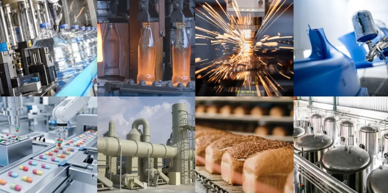
The nitrogen purity required for reactor blanketing is not determined by a single standard but by the sensitivity of the specific chemical process to oxygen and moisture contamination. Over-specifying the purity imposes unnecessary cost; under-specifying risks product degradation, catalyst poisoning, or unsafe atmosphere formation. The following framework maps Russian chemical industry application tiers to the correct nitrogen purity specification and the corresponding compressor and source configuration:
| Process Category |
N₂ Purity |
O₂ max |
Moisture |
Typical N₂ Source + Compressor |
| Flammable solvent storage blanketing |
99.5% |
5,000 ppm |
Ambient dew point |
PSA generator + lubricated DW (no downstream drying needed) |
| Petrochemical reactor blanketing |
99.9% |
1,000 ppm |
−40°C dew point |
PSA generator + lubricated or oil-free DW + mol sieve drier |
| Specialty chemical reactor (moisture-sensitive) |
99.99% |
100 ppm |
−60°C dew point |
PSA or ASU + oil-free DW + mol sieve drier |
| Organolithium / Grignard reactor |
99.999% |
10 ppm |
−70°C dew point |
ASU liquid N₂ + oil-free DW/ZW + mol sieve + getter purifier |
| Pharmaceutical API reactor |
99.999% |
10 ppm |
−70°C dew point |
ASU liquid N₂ + oil-free DW/ZW + full purification + GMP documentation |
Purity specifications are based on common Russian chemical industry practice and applicable GOST and EAC standards for each process category. The organolithium and pharmaceutical tiers require independent gas quality testing at the point of use rather than relying solely on source specification and compressor documentation.
Compressor Sizing for Nitrogen Blanketing Duty
Sizing the nitrogen blanketing compressor requires calculating the peak instantaneous nitrogen demand, not the average demand. The peak demand occurs during the most rapid vessel filling event, when incoming liquid displaces nitrogen from the blanket space at the highest possible rate. The calculation follows four steps that apply to any mode of blanket pressure control:
Peak Nitrogen Demand Calculation — Chemical Reactor Blanketing
1.
Maximum liquid filling rate: The fastest rate at which liquid can be charged into the reactor, in m³/h. This is typically the pump delivery rate or the gravity-flow rate from the highest connected vessel. For a 10 m³ reactor charged at a maximum rate of 5 m³/h: peak nitrogen displacement = 5 m³/h = 83 litres/min.
2.
Blanket space breathing losses: Nitrogen lost through vessel breathing as the liquid temperature changes during the day (thermal breathing) and through imperfect seals. Typical breathing loss for a well-sealed 10 m³ reactor: 5–15 litres/min. This adds to the filling displacement demand.
3.
Total peak demand: Filling displacement + breathing loss + 20% safety margin = approximately 115–120 litres/min = 0.115–0.12 m³/min at suction conditions for the example reactor.
4.
Delivery pressure: The blanket pressure setpoint plus the downstream line pressure loss from the compressor to the reactor inlet. For a 20 mbar blanket setpoint and 0.3 bar line losses in a typical chemical plant distribution system, the compressor delivery pressure is approximately 0.5–1.0 bar above the blanket setpoint — typically 1.5–5 bar for most blanket applications. At this moderate delivery pressure, a ZW series compressor is correctly matched for small and medium reactor blanket systems; a DW series machine serves larger multi-reactor manifold systems.
GOST and EAC Compliance for Nitrogen Blanketing at Russian Chemical Plants
The regulatory framework governing nitrogen blanketing systems at Russian chemical production facilities is more complex than for standard industrial gas installations. The blanketing system is part of the process safety architecture of a facility that is almost certainly classified as a hazardous production facility (OPO) under Federal Law No. 116-FZ, and the blanketing function itself may be classified as a safety instrumented function under the EAC standards for functional safety (GOST R IEC 61511). The key regulatory requirements that affect the compressor specification and documentation are:
A
GOST 12.1.011 — Explosion safety: Establishes the maximum permitted oxygen concentration in the vapour space of a vessel containing flammable materials (typically below 2% by volume for most flammable solvents, below 5% for some dusts). The nitrogen blanketing system must maintain the oxygen concentration below this limit at all operating conditions, including during liquid filling when the blanket is most challenged. The compressor must maintain blanket pressure during the maximum filling rate without allowing the oxygen concentration to rise above the limit, which requires that the compressor capacity exceed the maximum nitrogen displacement rate by a margin sufficient to account for the response time of the pressure controller and the compressor startup delay. For an automatic standby system, the standby start time must be included in the buffer vessel storage capacity calculation.
B
PB 09-563-03 — Explosive production safety rules: Requires that the nitrogen blanketing compressor system be documented in the process hazard analysis (PHA) as a protective layer against the identified explosion hazard. The compressor specification, including its rated flow rate, delivery pressure, and automatic standby start logic, must be documented in the PHA with the supporting calculation showing that the blanket is maintained within the explosion-safe oxygen concentration range throughout all credible operating scenarios. The compressor must be included in the facility’s preventive maintenance programme with inspection intervals specified in the PHA.
C
GOST R IEC 61511 — Functional safety: If the nitrogen blanketing function is assigned a Safety Integrity Level (SIL) in the process safety analysis, the compressor and associated pressure control system must be designed and maintained to achieve the required probability of failure on demand (PFD) for that SIL level. SIL 1 requires PFD below 0.1 (10% probability of failure when demanded); SIL 2 requires PFD below 0.01. An N+1 compressor arrangement with automatic standby start and proof testing at a defined interval typically achieves SIL 1 or SIL 2 for the mechanical blanketing function without additional redundancy. The proof test interval and the test method must be defined and followed; a compressor that has not been proof-tested according to its design basis loses its SIL certification for the purpose of the safety case.
D
TR CU 032/2013 — Pressure equipment conformity: The compressor and all downstream pressure components — buffer vessel, high-pressure manifold, control valves — above 0.05 MPa working pressure must carry EAC conformity certification under TR CU 032/2013. For nitrogen blanketing compressors typically operating at 1–10 bar delivery pressure this falls in the lower risk categories of the regulation (Category I or II), requiring declaration of conformity rather than third-party assessment — but the declaration must be based on documented compliance with the harmonised GOST standards for pressure equipment design and manufacture. Our supply package for nitrogen blanketing compressors includes the TR CU 032/2013 declaration of conformity, the compressor design pressure documentation, and the test certificates as standard.
Related Application · Plastics Manufacturing
Nitrogen Blanketing Logic in ISBM Preform Heating: Protecting Quality Through Inert Atmosphere
The protective inert atmosphere concept that underpins nitrogen blanketing of chemical reactors has a direct parallel in PET preform conditioning for injection stretch blow moulding (ISBM). In one-step ISBM, the preform is conditioned in the heating station immediately before the blowing station — the preform surface temperature must reach 90–110°C uniformly without surface oxidation that would cause yellowing or reduced clarity in the final bottle. Some high-clarity pharmaceutical and cosmetic bottle applications use a low-level nitrogen purge in the preform conditioning zone to prevent surface oxidation at the elevated conditioning temperature, applying exactly the same principle as reactor nitrogen blanketing: a controlled inert atmosphere prevents oxidation of the sensitive material surface. The pressure control logic is also analogous — the nitrogen flow rate is controlled to maintain a slightly positive overpressure in the conditioning zone, just as the blanketing compressor maintains a slightly positive nitrogen overpressure in the reactor vapour space. The scale and hazard level are very different, but the engineering principle — controlled inert gas overpressure to exclude oxidising atmosphere from a sensitive process zone — is identical. A chemical plant engineer who designs nitrogen blanketing systems for reactors will find the ISBM preform conditioning nitrogen specification immediately understandable.
Related equipment: One-step three-station ISBM machines for pharmaceutical and high-clarity PET bottle production — with nitrogen-purged preform conditioning applying the same inert atmosphere protection principle as chemical reactor nitrogen blanketing.
ISBM Machine ›injectionstretchblowmolding.com
FAQ — Nitrogen Blanketing Compressor for Chemical Reactors
Q1: Our reactor blanket compressor trips on high discharge temperature during summer and the standby starts automatically. The primary compressor restores normal operation within 30 seconds but the blanket pressure briefly falls to near zero. Is this a safety event that must be reported under Russian OPO regulations?
Yes — a brief loss of blanket pressure to near zero at a reactor handling flammable materials is a process safety event that must be evaluated against the criteria for OPO incident reporting under Federal Law No. 116-FZ and the Rostechnadzor reporting requirements for hazardous production facilities. Whether the event meets the threshold for mandatory reporting depends on whether the blanket pressure loss was accompanied by any measurable increase in oxygen concentration in the reactor vapour space — if the buffer vessel maintained the blanket above the minimum safe oxygen concentration throughout the 30-second compressor trip and standby start sequence, the event may be classified as a near-miss (otkloneniye) rather than an incident (avariynaya situatsiya). The evaluation must be documented in the OPO operations log regardless of the classification outcome, with the oxygen concentration data from the continuous analyser in the reactor vapour space (if installed) or a calculated estimate based on the buffer vessel volume, the leak rate, and the elapsed time without blanketing pressure. The root cause of the primary compressor’s high discharge temperature trip must also be investigated and corrected, and the finding documented. If the discharge temperature trip recurs without a verified root cause correction, Rostechnadzor would have grounds to require an independent safety audit of the blanketing system. Our engineering team provides root cause investigation support for OPO-registered nitrogen blanketing compressor events at Russian chemical plants.
Q2: We are designing a new specialty chemical plant with twelve reactors each requiring a 20 mbar nitrogen blanket at 50 litres per minute average demand. Should we use one central compressor serving all twelve reactors or individual nitrogen compressors for each reactor?
The central versus individual compressor decision for a twelve-reactor blanket system involves three engineering trade-offs that have no universal answer. Central compressor with manifold distribution produces lower capital cost per reactor served (one large DW machine versus twelve small ZW machines), lower maintenance burden (one preventive maintenance programme rather than twelve), and simpler instrumentation. However, a single compressor failure on a central system exposes all twelve reactors simultaneously — requiring either an N+1 standby for the central machine or individual buffer vessels per reactor sized to maintain the blanket for the duration of compressor repair and restart. Individual compressors per reactor provide independent redundancy — a failure on one ZW machine affects only that reactor — but the total capital and maintenance cost is higher and the pipe routing between twelve compressor locations and twelve reactors is more complex. For a specialty chemical plant where each reactor handles a different product at a different purity specification, individual compressors also allow each reactor’s blanket purity to be independently optimised: a reactor handling organolithium compounds can be served by a high-purity oil-free ZW machine while an adjacent reactor handling flammable solvents that need only 99.5% nitrogen is served by a lubricated and less expensive machine. The hybrid approach — two or three central DW machines serving reactor clusters of four, with individual buffer vessels at each reactor sized for 30 minutes of blanket maintenance — typically provides the best balance of capital cost, redundancy, and flexibility for a twelve-reactor specialty chemical plant.
Q3: Our reactor blanket nitrogen is supplied from liquid nitrogen dewars. We want to switch to an on-site compressor fed from a PSA generator to reduce cost. What purity can the PSA source deliver and will it meet our current 99.99% blanket specification?
A high-purity PSA nitrogen generator can deliver 99.99% purity at its rated flow rate, which is sufficient for the specialty chemical reactor blanketing tier at 100 ppm maximum oxygen. The critical constraints are that the PSA generator must be correctly sized with a safety margin above the peak blanket demand (the liquid filling displacement rate plus breathing losses), and that a molecular sieve drier is installed on the compressor discharge to achieve the −60°C dew point required at the specialty chemical tier — PSA nitrogen from a typical generator has a dew point of −40°C to −50°C without downstream drying, which may not meet the moisture specification if your current dewar-supplied liquid nitrogen is at −70°C dew point. The transition from liquid nitrogen to on-site PSA plus compressor requires an ATEX or GOST IEC 60079-rated installation design for the compressor room if any of your reactors are in classified hazardous areas, and the PSA generator itself must be located outside the classified zone unless specifically rated for the zone classification. Typical payback against delivered liquid nitrogen dewar cost for a system consuming above 30–50 Nm³/h of nitrogen is 18–30 months. Our engineering team provides a detailed economic comparison and PSA plus compressor system specification from your current nitrogen consumption data and blanket specifications.
Nitrogen Blanketing Compressors
ZW and DW Series for Chemical Reactor Nitrogen Blanketing
ZW series (2–75 kW, 1–30 MPa) and DW series (55–350 kW, 1–30 MPa) nitrogen blanketing compressors for chemical reactor and storage vessel applications — lubricated and oil-free cylinder options, N+1 automatic standby configuration, OPO and TR CU 032/2013 documentation package. Provide your reactor volume, maximum liquid filling rate, blanket pressure setpoint, nitrogen purity requirement, and hazard classification for a complete blanketing system specification within 48 hours.