Practical Maintenance · Valve Failure · Discharge Temperature · Fault Detection · Gas Compressors
A rising discharge temperature is the earliest on-line warning of compressor valve deterioration — but the temperature alone does not tell you which valve is failing or whether the problem is a suction valve or a discharge valve. Read correctly, the pattern of temperature changes across the compressor stages and the profile of valve body temperatures on the cylinder head pinpoints the failing valve to within a single assembly, allowing targeted maintenance rather than a full cylinder teardown. This guide shows how to read the discharge temperature evidence, combine it with valve body temperature checks, and decide whether the compressor can continue running or needs immediate attention.
✓ Suction vs Discharge Valve
✓ Run vs Shut Decision
✓ All Gas Services
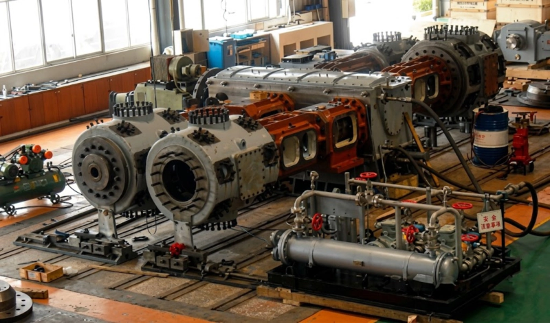
Reciprocating compressor undergoing acceptance test run — stage discharge temperatures, inter-stage pressures, and valve body surface temperatures are recorded at commissioning to establish the baseline against which all subsequent readings are compared. The difference between a temperature reading and its commissioning baseline is the primary tool for detecting valve deterioration before a failure occurs in service.
Why Discharge Temperature Is the Universal Valve Condition Indicator
A gas valve in a reciprocating compressor that is leaking — whether suction or discharge — allows gas to flow in the wrong direction through the valve when it should be closed. This bypass flow converts compression work into heat without delivering useful gas output. The heat appears as an elevated temperature in the gas stream leaving that stage, measured at the stage discharge temperature sensor. Since the compressed gas carries the heat signature of every valve in the stage, the discharge temperature is the aggregate indicator of all valve condition in that stage — and a rise in discharge temperature above the commissioning baseline is the first measurable evidence that a valve is developing a leak.
The relationship between discharge temperature rise and valve leak severity is consistent enough across different gas services and compressor types to allow the following general rules to be applied at any ZW, DW, LW, or 4MW series installation:
| Rise Above Baseline | Valve Condition Assessment | Recommended Action |
|---|---|---|
| +3°C to +8°C | Early seat wear; trace leakage beginning | Monitor trend; plan inspection at next scheduled window |
| +8°C to +20°C | Moderate leakage; 5–15% efficiency loss | Schedule inspection within 500–1,000 h; reduce to standby if available |
| +20°C to +40°C | Significant leakage; 15–30% efficiency loss | Inspect within 200 h; switch to standby compressor if available |
| Sudden >+20°C | Valve plate fracture or major seat damage | Trip compressor immediately — do not restart before inspection |
All rises measured against the commissioning baseline at the same suction conditions, discharge pressure, and cooling water temperature. Any sudden step change — regardless of magnitude — warrants immediate investigation regardless of absolute temperature.
Distinguishing Suction Valve Failure from Discharge Valve Failure
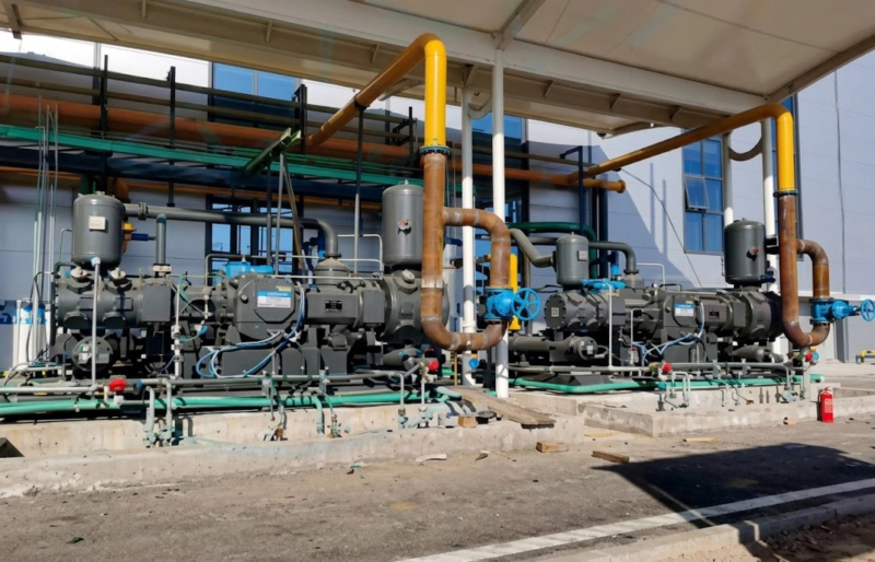
The discharge temperature rise tells you that a valve in the stage is leaking — but it does not immediately identify whether the failing valve is a suction valve or a discharge valve. This distinction matters for two reasons: it determines the urgency of shutdown (discharge valve leakage is more severe at the same temperature rise) and it focuses the maintenance effort on the correct assembly. Two tools distinguish between the two failure modes:
In a two-stage compressor, track the inter-stage pressure between stages at constant suction and final discharge conditions.
Use an infrared thermometer or thermal imaging camera to measure the external surface temperature of each valve body cover on the cylinder head — both suction and discharge valves.
The Five-Minute On-Site Diagnosis Procedure
When a discharge temperature alarm triggers or a rising temperature trend is observed, the following five-minute procedure — requiring only an infrared thermometer and access to the stage pressure gauges — localises the fault to a specific valve assembly before any cylinder is opened:
Run vs Shut Decision: A Practical Framework
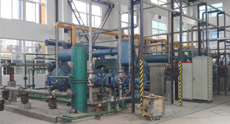
The decision to keep a compressor running with a known valve fault — accepting the energy efficiency loss and the risk of further deterioration — versus shutting down immediately for repair, depends on four factors. Each factor increases or decreases the acceptable run time before valve replacement:
| Factor | Run Extended | Shut Sooner |
|---|---|---|
| Temperature rise rate | Stable, not accelerating | Accelerating rise (valve deteriorating fast) |
| Gas service | Nitrogen, argon, refrigerant | Oxygen service — any discharge valve fault triggers immediate shutdown |
| Standby availability | Standby compressor available | No standby — any trip stops supply |
| Fault type | Gradual seat leakage (slow onset) | Sudden rise — plate fracture suspected |
| Spare valve set on-site | Yes — plan repair within 200–500 h | No — order parts before extending run |
For oxygen service: any detected discharge valve fault requires immediate shutdown and inspection before restart, regardless of temperature rise magnitude. A discharge valve with a cracked plate in oxygen service can send metal fragments into the cylinder bore — the downstream consequences (bore scoring, piston damage) are more severe than the valve replacement itself. The discharge temperature rise threshold for action in oxygen service is therefore effectively zero for sudden-onset events.
Blow Air Pressure Curve as the ISBM Equivalent of Discharge Temperature Trending
In an injection stretch blow moulding (ISBM) machine, the equivalent of discharge temperature trending for the industrial gas compressor is the blow air pressure curve monitoring during the moulding cycle. The blow air pressure at the mould cavity rises, holds, and vents in a defined profile for each bottle size — and any check valve or blow air circuit valve that is leaking changes this profile measurably. A slower pressure rise indicates a leaking check valve upstream of the blow station; a faster pressure decline during the hold phase indicates a leaking blow valve or mould seal. In both the industrial compressor and the ISBM machine, the performance parameter that is easiest to monitor continuously — discharge temperature in one case, blow pressure curve in the other — is the earliest and most sensitive indicator of valve condition. The diagnostic logic is identical: establish a commissioning baseline, track the deviation, localise the fault using a secondary temperature or pressure measurement, and decide run-to-plan or immediate repair based on the trend and the gas service risk level.
FAQ — Valve Failure Detection by Discharge Temperature
Valve Replacement Sets — ZW, DW, LW, 4MW Series
Complete suction and discharge valve replacement sets for all stages of ZW, DW, LW, and 4MW series compressors — valve plates, seats, springs, lift limiters, and gaskets. Stocked in Russia for 24–72 hour dispatch. Specify compressor model, stage number, and gas service when ordering.