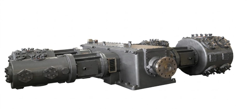
Practical Guide · Nameplate Reading · Model Designation · ZW DW LW 4MW · Spare Parts
Standing in front of an unfamiliar compressor on a Russian industrial site, the nameplate is the fastest route to understanding what you have, whether it is correctly specified for its duty, and what spare parts to order. A ZW, DW, LW, or 4MW compressor nameplate encodes the frame type, flow rate, discharge pressure, and gas service in a structured format that can be read systematically in under a minute — if you know the convention. This guide decodes every field on a Russian industrial gas compressor nameplate, from the series letters through the slash-separated capacity numbers to the gas service suffix, and shows what each tells you about the machine and its maintenance requirements.
✓ Series Code Meaning
✓ Flow / Pressure Numbers
✓ Service Suffix Letters
✓ Spare Parts Identification
The Nameplate Structure at a Glance
Every ZW, DW, LW, and 4MW series compressor nameplate carries the model designation in a structured format. Before reading the individual fields, it helps to see the complete structure laid out:
DW − 10 / 250 — O
DW
Series code
Frame + capacity class
−
Series-to-capacity separator
10
Flow rate
10 m³/min at suction
/
Flow-to-pressure separator
250
Discharge pressure
250 bar (or kgf/cm²)
O
Gas service suffix
Oxygen service
Reading: DW series (opposed-balance, medium capacity), 10 m³/min suction flow, 250 bar discharge pressure, oxygen service. Oil-free cylinder, GOST 12.2.052 compliant, virgin PTFE rings, copper-free construction.
Reading the Series Code: ZW, DW, LW, 4MW

The series code is always the first element of the model designation and encodes two properties simultaneously: the frame type (which determines vibration behaviour and suitability for rigidly-piped installation) and the capacity class (which indicates the power range). Reading the series code tells you everything about the mechanical architecture of the compressor without opening any documentation:
ZW
Z = smallest capacity class · W = horizontal cylinders · L-type frame (not opposed-balance)
Power range 2–75 kW. L-type frame with cylinders at an angle to each other — suitable for small compressors with flexible hose connections, not for permanently rigidly-piped installations above 75 kW. Piston ring maintenance interval: 4,000–8,000 h. Valve inspection interval: 2,000–5,000 h. If you see ZW on a nameplate connected to rigid process pipework above 75 kW, this is an installation error requiring engineering review.
DW
D = medium capacity class · W = horizontal cylinders · Opposed-balance frame
Power range 55–350 kW. Two cylinder columns on opposite sides of the crankcase cancel primary inertia forces — the standard specification for permanently rigidly-piped industrial gas installations in Russia at this power level. A DW nameplate tells you: inter-stage coolers will be present (multi-stage), the distance piece is double-compartment vented (for gas services above 0.5 MPa), and GOST-R certification is available for O₂, N₂, Ar, CO₂, and NH₃ service depending on the suffix.
LW
L = large capacity class · W = horizontal cylinders · Opposed-balance frame
Power range 160–500 kW. Same opposed-balance W-type frame geometry as the DW series but with larger cylinder bores and longer stroke. An LW nameplate at the same power as a DW nameplate indicates a lower piston speed design — typically chosen for extended valve and ring intervals. In the 160–350 kW overlap range, an LW machine and a DW machine of the same power have identical vibration performance from the frame; the LW has larger bores running at lower speed.
4MW
4 = four columns · M = symmetrically balanced · W = horizontal
Power range 350–1,600 kW. Four cylinder columns in two opposed pairs cancel both primary forces and primary couples — the highest dynamic balance standard in reciprocating compressor design. A 4MW nameplate immediately tells you this is a large machine, almost certainly an ammonia refrigeration or large industrial gas compressor, with a crankshaft size number appearing before the hyphen (e.g. 4M10- means 100 mm throw radius). This machine will have four active cylinder heads visible on the frame.
Reading the Flow Rate and Pressure Numbers
The two numbers separated by a slash encode the compressor’s capacity. The number before the slash is the volumetric flow rate at suction conditions in m³/min; the number after the slash is the discharge pressure in bar (or kgf/cm² in older documentation — numerically equivalent within rounding). These numbers immediately place the machine in its application context:
Pressure tells you the application
/6 to /16: low-pressure industrial gas supply or refrigerant compression. /30 to /100: medium-pressure process gas or nitrogen distribution. /150 to /250: high-pressure nitrogen or oxygen pipeline or cylinder filling. /300 to /350: ultra-high-pressure cylinder filling for speciality gases. A pressure above /30 indicates multi-stage design and the presence of inter-stage coolers on the machine.
Flow rate tells you the power class
Flow rate and discharge pressure together determine the compression power. As a rough guide at moderate pressures: 0.5–2 m³/min ∴ 5–30 kW range; 2–10 m³/min ∴ 30–110 kW range; 10–40 m³/min ∴ 110–350 kW range; above 40 m³/min ∴ 350–500 kW LW or 4MW territory. These are approximate — the discharge pressure also determines power, but a high flow rate at a glance signals a large machine.
Flow rate condition
The flow rate is at the first-stage suction conditions: atmospheric pressure (0.101 MPa) and 20°C unless the nameplate or datasheet specifies otherwise. If the machine draws suction from an elevated pressure source — for example, as a booster compressor taking suction from a 0.5 MPa nitrogen pipeline — the actual volumetric flow from the source is lower than the nameplate number, but the mass flow rate and delivery capacity remain as designed.
Pressure units: bar vs kgf/cm²
Older nameplates use kgf/cm² (technical atmospheres); newer ones use bar or MPa. 1 kgf/cm² = 0.981 bar ≈ 1 bar. For most practical purposes they are interchangeable. A nameplate reading /250 can be read as 250 bar or 250 kgf/cm² — the difference is less than 2% and is not significant for spare parts identification or duty assessment.
Reading the Gas Service Suffix
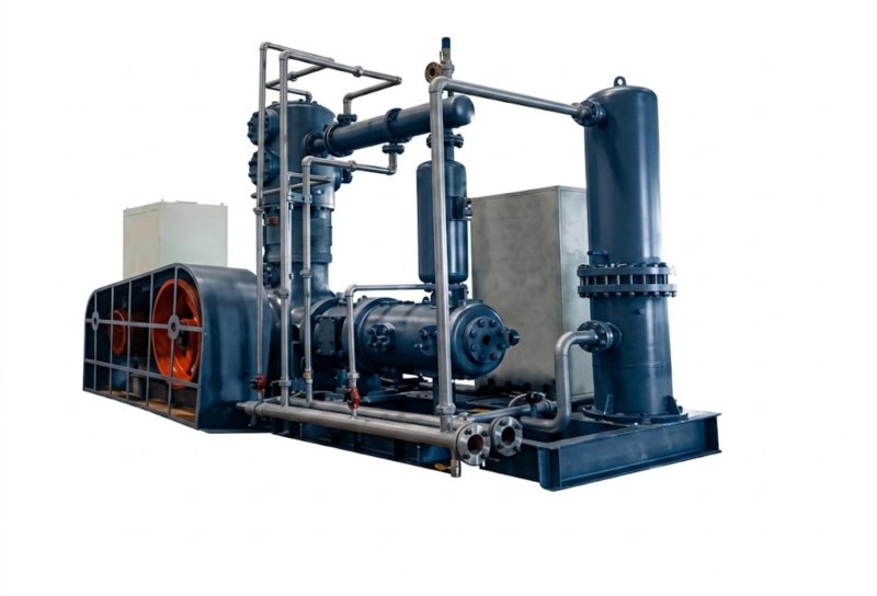
The letter or letters after the pressure number — if present — indicate the gas service and any special design features. This suffix is the most practically important part of the nameplate for maintenance and spare parts work, because it determines which ring materials are fitted and what safety requirements apply:
| Suffix |
Gas Service |
Key Implications for Maintenance |
| O |
Oxygen — GOST 12.2.052 |
Virgin PTFE rings mandatory. All tools and parts must be degreased before cylinder contact. No petroleum-based thread compounds. Akt obezzhirivaniya required after any cylinder access. |
| A |
Ammonia — GOST 26790 |
NH₃-compatible seals and gaskets. No copper alloys in wetted parts. Carbon-filled or bronze-filled PTFE rings acceptable (not virgin-only as in O service). Refrigerant service: check two-stage arrangement if evaporating below −28°C. |
| X |
Refrigerant (HFC/HCFC) |
HFC-compatible lubricant (POE or PAG oil, not mineral oil). Ring and packing materials compatible with HFC service. Check refrigerant type on site documentation — the X suffix covers multiple refrigerants. |
| B |
Booster configuration |
Suction is above atmospheric pressure. The flow/pressure numbers refer to actual suction and discharge conditions, not atmospheric suction. Do not use the nameplate flow number as if it were atmospheric suction flow when sizing replacement or spare machines. |
| (none) |
Nitrogen / argon / inert gas |
No gas-service suffix typically indicates nitrogen or argon service — the most common service for DW and LW machines without an O or A suffix. Virgin or filled PTFE rings both acceptable. Verify gas service from the equipment passport if there is any uncertainty before ordering rings. |
Suffix conventions vary between production years and between manufacturers. The table reflects the most common convention for ZW, DW, LW, and 4MW series machines. When in doubt, cross-reference the nameplate designation against the equipment passport — the passport is the authoritative document specifying all materials of construction and the gas service for the specific unit.
Using the Nameplate to Order Spare Parts
The nameplate model designation is the starting point for spare parts identification — but it is not sufficient on its own for precise ordering. Within a given designation (e.g. DW-10/250-O), the bore diameter, stroke, and stage count may vary between production years. The complete information needed to order the correct spare parts is:
1
Model designation from nameplate (e.g. DW-10/250-O) — narrows the search to the correct series and capacity range.
2
Serial number from nameplate — identifies the specific unit and links to the factory build record, allowing exact bore, stroke, and parts specification to be retrieved from manufacturer records.
3
Bore diameter and stroke from nameplate or passport — definitively identifies the piston ring and packing ring dimensions. Two DW-10/250-O machines can have different bore sizes if manufactured in different years; the ring dimensions differ accordingly.
4
Stage number — specify which stage the spare is for (1st stage, 2nd stage, etc.). Bore diameter and ring dimensions differ between stages in a multi-stage machine; a ring set for the 1st stage will not fit the 2nd stage.
Related Application · Plastics Manufacturing
Reading an ISBM Machine Nameplate: The Same Structured Logic
The structured nameplate convention used for ZW, DW, LW, and 4MW compressors has a direct parallel in injection stretch blow moulding (ISBM) machine model designations. An ISBM model number encodes station count (one-step = injection + conditioning + blowing in one machine), maximum bottle capacity (in litres), and output rate (cavities or bottles per hour) in a structured code that experienced operators read immediately. Just as a maintenance engineer reading «DW-10/250-O» knows to expect oil-free cylinders, virgin PTFE rings, and GOST 12.2.052 documentation, an ISBM operator reading the machine designation knows immediately the preform compatibility, the blow air pressure requirement, and the mould changeover time. In both cases the nameplate encodes what you need to know for operation, maintenance, and spare parts ordering — if you know how to read it.
Related equipment: One-step three-station ISBM machines for PET bottle production — with a model designation that encodes station count, bottle capacity, and output rate in the same structured format as the ZW/DW/LW/4MW compressor code.
ISBM Machine ›injectionstretchblowmolding.com
FAQ — Compressor Nameplate and Model Designation
Q1: The nameplate is unreadable or missing — how do I identify the compressor and order spare parts?
If the nameplate is missing or corroded beyond reading, spare parts can still be identified from physical measurements. For piston rings: measure the cylinder bore diameter with a bore gauge or inside micrometer — the bore diameter directly determines the ring outside diameter. For rod packing: measure the piston rod diameter in the packing contact zone — this determines the ring inside diameter. For valves: remove a valve assembly and measure the seat outer diameter, port geometry, and plate lift — these dimensions identify the valve type from the parts catalogue. Photographs of the cylinder head, valve cover, and distance piece assembly sent to our technical support team allow identification of the compressor series and generation from the external geometry in most cases. The equipment passport — if available in the site documentation archive — contains the bore, stroke, and stage count that define all consumable part dimensions without any physical measurement.
Q2: The nameplate says DW but the compressor is connected to oxygen pipework — does it have the correct rings?
A DW nameplate without the -O suffix does not guarantee that the compressor has oil-free cylinders with virgin PTFE rings — the suffix is a design-at-manufacture indicator. If a DW series compressor is operating in oxygen service above 0.5 MPa, it must have been configured with oil-free cylinders at manufacture and the -O suffix should appear on the nameplate or in the equipment passport. If the nameplate lacks the -O suffix but the machine is on an oxygen system, this is a serious discrepancy that requires immediate investigation: either the machine was correctly built for oxygen service but incorrectly marked, or it was not built for oxygen service and is operating in violation of GOST 12.2.052. Do not assume the rings are correct from the nameplate alone if the suffix is missing — open the cylinder and inspect the ring material, or request the factory build record from the equipment serial number.
Q3: What does the number before the hyphen mean in a 4MW designation like 4M10-100/210?
In the 4MW series, the number immediately before the hyphen (the «10» in 4M10-100/210) designates the crankshaft throw radius in centimetres. A throw radius of 10 cm (100 mm) means the piston travels 200 mm total stroke (2 × throw). The throw radius determines the displacement per cylinder revolution and, combined with the cylinder bore diameter, the volumetric flow at the rated speed. Larger throw numbers (8, 10, 12, 16) indicate progressively larger frame sizes and higher power classes. The 4M10 frame at 100 mm throw is the most common 4MW configuration in Russian industrial refrigeration; the 4M16 frame (160 mm throw) represents the largest standard 4MW configuration at 1,200–1,600 kW. When ordering spare parts for a 4MW machine, the frame size number (8, 10, 12, or 16) is an essential part of the specification in addition to the stage count and bore diameter.
Spare Parts and Technical Support
Identify Parts from Your Nameplate — ZW, DW, LW, 4MW Series
Send us the nameplate designation, serial number, and the stage you need parts for — our Russian technical team identifies the correct piston rings, rod packing, valve sets, and gaskets for your specific unit and dispatches within 24–72 hours. For unreadable nameplates, send photographs and bore measurements.