Technical Knowledge · Model Nomenclature · Series Identification · Compressor Selection · Russia
The ZW, DW, LW, and 4MW series designations used for Russian reciprocating gas compressors encode the frame type, cylinder arrangement, capacity class, and gas service directly in the model number. Understanding this naming convention allows an engineer or procurement specialist to read the mechanical properties of a compressor from its series code alone — without access to the technical datasheet. This guide decodes the full ZW, DW, LW, and 4MW model designation system, including the numerical and letter suffixes that appear in complete model numbers such as ZW-0.6/350, DW-10/250, LW-40/8, and 4M10-100/210.
✓ Series Letter Codes
✓ Capacity / Pressure Suffixes
✓ Full Model Number Examples
✓ Frame Type vs Gas Service
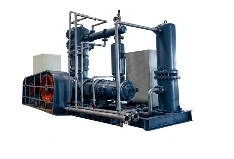
LW series reciprocating compressors — the series designation encodes frame type (opposed-balance horizontal W-type), capacity class (L = large), and cylinder arrangement. A complete LW model number such as LW-40/8 further specifies the flow capacity (40 m³/min) and discharge pressure (8 MPa), allowing the full mechanical specification to be reconstructed from the model code alone by an engineer familiar with the Russian compressor designation convention.
The Structure of a Russian Reciprocating Compressor Model Number
A complete Russian reciprocating compressor model designation has two parts: the series code (letters, sometimes preceded by a number) that identifies the frame type and capacity class, and the capacity suffix (numbers separated by a slash) that specifies the flow rate and discharge pressure for that particular machine within the series. The general format is:
[Series Code] – [Flow Rate] / [Discharge Pressure]
ZW
Series code:
frame + capacity class
–
/
350
Discharge pressure
(kgf/cm² or bar)
Example: ZW-0.6/350 — ZW series, 0.6 m³/min flow, 350 bar discharge pressure
The flow rate is typically expressed in m³/min at the first-stage suction conditions (atmospheric pressure and 20°C unless otherwise specified in the datasheet). The discharge pressure is expressed in kgf/cm² in older Russian documentation and in bar or MPa in more recent designations — the numerical value is the same within rounding (1 kgf/cm² ≈ 0.098 MPa ≈ 0.981 bar). For the 4MW series, the format differs slightly and is explained separately below.
Decoding the Series Letter Codes

ZW
Z = Capacity class (small) · W = Horizontal cylinder arrangement
L-type frame · 2–75 kW · Single or two-stage · Nitrogen, oxygen, argon, CO₂
The letter Z designates the smallest capacity class in the Russian reciprocating compressor series family. The letter W (from the Russian convention for the horizontal cylinder arrangement) indicates that the cylinders are oriented horizontally. The ZW series uses an L-type frame with cylinders arranged at an angle to each other rather than in the opposed-balance configuration of the DW and LW series — as explained in blog-19, this makes the ZW frame suitable for small compressors with flexible hose connections but not for large, permanently rigidly-piped installations. ZW designations run from ZW-0.15/350 (smallest, for high-pressure cylinder filling at very low flow) to ZW-6/250 (largest in the series, approaching the lower end of the DW range).
Example: ZW-0.6/350 — 0.6 m³/min suction flow, 350 bar discharge. Typical for medical oxygen or industrial gas cylinder filling stations.
DW
D = Capacity class (medium) · W = Horizontal opposed-balance
Opposed-balance W-type frame · 55–350 kW · Multi-stage · All gas services
The letter D designates the medium capacity class. Combined with W (horizontal), the DW designation identifies the opposed-balance horizontal frame — two cylinder columns arranged on opposite sides of the crankcase, with pistons moving in opposite directions to cancel primary inertia forces. The DW series is the workhorse specification for permanently rigidly-piped industrial gas compressor installations in Russia at 55–350 kW: nitrogen and oxygen boosters for air separation plants, medical gas cylinder filling, argon recovery, and refrigerant compression (NH₃, R-22 legacy systems) at medium scale. DW designations cover a wide range of pressures, from low-pressure nitrogen supply (DW-40/8, 8 bar discharge) to high-pressure cylinder filling (DW-1.5/200, 200 bar discharge).
Example: DW-10/250 — 10 m³/min suction flow, 250 bar discharge. Typical for nitrogen cylinder filling or high-pressure nitrogen supply to a petrochemical plant.
LW
L = Capacity class (large) · W = Horizontal opposed-balance
Opposed-balance W-type frame · 160–500 kW · Multi-stage · All gas services
The letter L designates the large capacity class. The LW frame geometry is identical to the DW — horizontal opposed-balance W-type — but with larger cylinder bores, longer stroke, and higher displacement per revolution than the equivalent DW unit at similar power. In the overlapping power range of 160–350 kW, an LW unit typically has a larger bore at a lower piston speed than an equivalent DW unit, which can extend valve and ring service intervals. At its upper end (350–500 kW), the LW series addresses installations where the DW capacity is insufficient but the full symmetrically-balanced 4MW frame is not yet required. LW designations include LW-20/16 (air separation nitrogen supply), LW-40/8 (large nitrogen distribution system), and LW-6/320 (high-pressure oxygen cylinder filling).
Example: LW-40/8 — 40 m³/min suction flow, 8 bar discharge. Typical for large nitrogen distribution supply at an industrial park or petrochemical complex.
4MW
4 = Four cylinder columns · M = Symmetrically balanced · W = Horizontal
Symmetrically balanced 4-column frame · 350–1,600 kW · NH₃ / refrigerant primary
The 4 designates four cylinder columns arranged around the crankcase. The M (from the Russian engineering term for symmetrically balanced) indicates that the four columns are arranged in two opposed pairs, cancelling both primary forces and primary couples — the highest level of dynamic balance achievable in a reciprocating compressor frame. The W designates horizontal cylinder orientation. The 4MW series is the standard specification for large industrial refrigeration compressors (NH₃, R-22, CO₂ transcritical) and large industrial gas compressors (nitrogen, oxygen) above 350 kW in Russia.
The 4MW model number format differs from the ZW/DW/LW convention: it uses the format 4M[frame size]-[flow rate]/[pressure]. The frame size number (8, 10, 12, 16) designates the crankshaft throw radius in centimetres, which determines the displacement per cylinder and the power class of the frame.
Example: 4M10-100/210 — 4MW frame with 100 mm crankshaft throw, 100 m³/min flow (at suction conditions), 210 bar discharge. A large nitrogen compressor or high-capacity refrigerant machine.
Additional Letter Suffixes in Complete Model Numbers
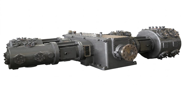
Beyond the base series code and the flow/pressure suffix, complete model designations may include additional letters that indicate the gas service, stage count, or special design features. The most commonly encountered suffixes in Russian industrial practice are:
| Suffix |
Meaning |
Example |
| O |
Oxygen service — oil-free cylinders, GOST 12.2.052 compliant, virgin PTFE rings, copper-free construction |
ZW-0.6/350-O — oxygen cylinder filling |
| A |
Ammonia service — NH₃-compatible materials, ammonia-rated seals, no copper alloys |
4M10-100/8-A — large ammonia refrigeration |
| X |
Refrigerant service (general) — used for HFC and HCFC refrigerant compressors where the A suffix is not used |
DW-20/14-X — R-22 or R-404A refrigerant |
| 2 |
Two-stage compound configuration — low-stage and high-stage cylinders in one frame or one unit designated as low-stage in a two-unit system |
DW-20/8-A-2 — two-stage NH₃ low-stage unit |
| B |
Boost (booster) configuration — suction pressure above atmospheric; the flow/pressure suffix refers to the inlet and outlet pressures rather than atmospheric suction |
ZW-0.6/350-B — nitrogen booster from pipeline pressure to cylinder fill pressure |
Suffix conventions vary between manufacturers and between generations of the same series. Always verify the suffix meaning against the specific manufacturer’s datasheet when ordering spare parts or replacement units. The series code (ZW, DW, LW, 4MW) and the flow/pressure numbers are standardised; the letter suffixes after the slash-separated numbers are manufacturer-specific.
Series Selection Guide: What the Model Code Tells You
Frame type from code
ZW = L-type (not opposed-balance). DW and LW = opposed-balance W-type (primary forces cancelled). 4MW = symmetrically balanced (forces and couples cancelled). The frame type determines whether the compressor is suitable for permanently rigidly-piped installation (DW, LW, 4MW) or requires flexible connections (ZW).
Power class from code
ZW: 2–75 kW. DW: 55–350 kW. LW: 160–500 kW. 4MW: 350–1,600 kW. Overlapping ranges between DW/LW and LW/4MW mean that a given duty point may be achievable with either series — the choice is determined by capital cost, maintenance interval preference, and site vibration requirements.
Pressure range from numbers
The slash-separated pressure number (e.g. /8, /250, /350) immediately tells you the application pressure class: /6–/16 = low-pressure industrial gas supply or refrigerant compression. /30–/100 = medium-pressure process gas or nitrogen supply. /150–/350 = high-pressure cylinder filling or breathing air. Above /350 = specialist ultra-high-pressure applications.
Stage count from flow/pressure ratio
The ratio of discharge pressure to suction pressure (typically atmospheric = 1 bar) indicates the minimum number of stages: pressure ratios below 8:1 can be single-stage; 8:1 to 40:1 typically two-stage; above 40:1 three or four stages. A ZW-0.6/350 at 350:1 overall ratio is a three or four-stage machine. A DW-40/8 at 8:1 is likely single or two-stage.
Related Application · Plastics Manufacturing
Reading ISBM Machine Model Designations: A Parallel Naming Logic
Just as the ZW/DW/LW/4MW compressor designation encodes frame type, capacity class, and operating pressure in a structured code, injection stretch blow moulding (ISBM) machine model designations encode the number of stations, output capacity, and preform compatibility in their own structured format. An ISBM model number such as «3-Station 2L» tells the experienced operator that the machine has three stations (injection, conditioning, blowing in one cycle), produces bottles up to 2-litre capacity, and uses a specific preform geometry — just as ZW-0.6/350 tells a compressor engineer the frame type, flow rate, and pressure class without opening the datasheet. Both naming conventions reward engineers who take the time to learn their structure; both encode the most purchase-critical information — capacity and operating range — directly in the code that appears on every quotation, order, and nameplate.
Related equipment: One-step three-station ISBM machines for PET bottle production — with a model designation structure that encodes station count and bottle capacity in a format analogous to the ZW/DW/LW/4MW compressor code.
ISBM Machine ›injectionstretchblowmolding.com
FAQ — ZW, DW, LW, and 4MW Model Designations
Q1: The flow rate in the model number is at atmospheric suction — how do I convert this to actual delivery at my operating conditions?
The flow rate in the model designation (e.g. 10 m³/min in DW-10/250) is at standard suction conditions: 0.101 MPa (atmospheric) and 20°C. If your suction source is at a pressure above atmospheric — for example, taking nitrogen from a pipeline at 0.5 MPa — the actual volumetric flow from the source is lower, but the mass flow and delivery capacity at the outlet pressure is the same. For booster applications (suffix B), the model designation flow refers to the actual suction conditions at the booster inlet pressure, not atmospheric. The delivery mass flow (kg/min or Nm³/min at standard conditions) is the most useful specification for comparing compressors across different suction conditions; it can be calculated from the volumetric flow using the gas density at suction conditions. Our engineering team provides delivery calculations at specified suction and discharge conditions as part of the compressor selection process.
Q2: Can a DW series compressor be respecified for a different gas by changing the suffix?
Changing the gas service of an existing compressor — for example, from nitrogen to oxygen service — is more than a suffix change: it requires a physical modification of the machine to meet the requirements of the new gas service. Converting a DW nitrogen compressor to oxygen service (DW suffix O) requires at minimum: degreasing all oxygen-wetted components to GOST 12.2.052 standard; replacing any non-PTFE ring materials with virgin PTFE; verifying that all wetted metal components are copper-free; re-routing the distance piece vent line to comply with oxygen safety requirements; and obtaining a new GOST-R certification for oxygen service. It may also require replacing inter-stage cooler tubes with stainless steel if the existing carbon steel tubes are considered unacceptable for oxygen service at the operating pressure. A conversion from nitrogen to ammonia service (suffix A) similarly requires verifying material compatibility for all seals, gaskets, and internal components, since ammonia attacks some PTFE compounds and many elastomers. Gas service conversions should always be reviewed by the compressor manufacturer before proceeding.
Q3: How do I identify the correct spare parts from a model designation alone?
The model designation alone is a starting point for spare parts identification but is not sufficient on its own. Within a given series (e.g. DW-10/250), the cylinder bore sizes, stroke, number of stages, and internal geometry may vary between production years and between individual units of the same nominal specification as the manufacturer optimises the design over time. The definitive source for spare parts identification is the compressor serial number combined with the equipment passport (pasport), which specifies the exact bore, stroke, stage count, and all consumable part dimensions for that specific machine. When ordering spare parts — piston rings, rod packing, valve assemblies, gaskets — always provide both the model designation and the serial number. If the serial number is unavailable, the nameplate data (bore and stroke dimensions) allows correct spare parts identification from our parts catalogue. Our Russian technical support team can assist with spare parts identification from model designation, serial number, or equipment passport data.
Full Series Range
ZW, DW, LW, and 4MW Series Compressors
Complete range of ZW, DW, LW, and 4MW series reciprocating compressors for nitrogen, oxygen, argon, CO₂, NH₃, and refrigerant service — from 2 kW small cylinder filling to 1,600 kW industrial refrigeration. GOST-R certified. Full Russian documentation. Send your duty specification for model selection and quotation within 48 hours.