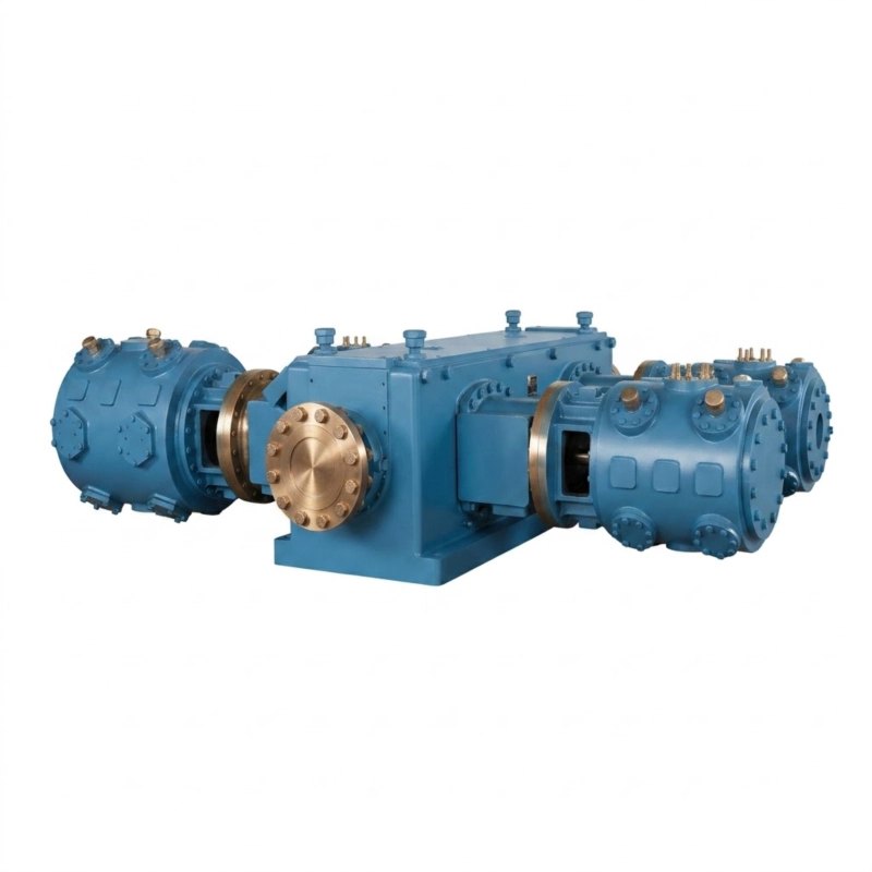
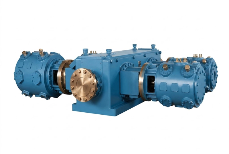
Product Overview: What Is the 4MW Series CO₂ Compressor?
The 4MW series carbon dioxide compressor is a four-column opposed-balance reciprocating piston compressor engineered specifically for mid-to-large volume CO₂ compression in industrial process applications. The designation “4MW” denotes the four-column (four-throw) crankshaft arrangement in which paired cylinders act on opposing sides of the crankshaft, cancelling primary inertia forces and delivering exceptionally smooth, low-vibration operation without the heavy reinforced foundations required by less balanced configurations.
Manufactured to API 618 Fifth Edition at our production facility in Russia, the 4MW series is a direct-performance equivalent to internationally recognised designs including the Ariel JGC series, Dresser-Rand (Siemens Energy) HOSS and HOS series, Neuman & Esser PCL and PCH series, and Burckhardt Laby series. Our compressors are not copies or imitations of these products; we reference these brands solely to assist engineers and procurement professionals in cross-referencing performance classes during the selection process. All 4MW units are original designs manufactured under our own engineering standards.
Industries served: Food-grade CO₂ liquefaction, dry ice production, EOR carbon dioxide injection, CCS/CCUS geological storage, chemical synthesis (urea, methanol, supercritical extraction), carbon capture from power and cement plants, industrial gas supply and distribution.
Technical Specifications — 4MW Series (Mid-to-High Pressure CO₂)
The table below covers the full 4MW series product range for medium-to-high pressure CO₂ service (discharge pressure 3.0–4.0 MPa). All models feature four-column four-stage configuration. Custom flow rates and pressures outside this matrix can be engineered to order.
| No. |
Model |
Type |
Flow (m³/min) |
Pressure (MPa) |
Dimensions L×W×H (mm) |
Weight (t) |
Power (kW) |
Voltage (V) |
| 26 |
4MW-85/40(30) |
4-column 4-stage |
85 |
4.00 (3.00) |
6400×3300×2800 |
26.00 |
1,000 |
6K/10K |
| 27 |
4MW-90/40(30) |
4-column 4-stage |
90 |
4.00 (3.00) |
6400×3300×2800 |
26.00 |
1,050 |
6K/10K |
| 28 |
4MW-100/40(30) |
4-column 4-stage |
100 |
4.00 (3.00) |
6400×3300×2800 |
26.50 |
1,100 |
6K/10K |
| 29 |
4MW-120/40(30) |
4-column 4-stage |
120 |
4.00 (3.00) |
6800×3900×3200 |
28.50 |
1,250 |
6K/10K |
| 30 |
4MW-150/40(30) |
4-column 4-stage |
150 |
4.00 (3.00) |
8500×3900×3200 |
30.00 |
1,700 |
6K/10K |
Note: Pressure notation 4.00(3.00) MPa indicates dual-pressure design capability — 4.0 MPa maximum / 3.0 MPa standard operating. Dimensions are for main unit only, excluding auxiliary skid systems. Custom frame sizes available upon request. Note: Units rated 11–3,000 kW can be designed and manufactured to order.
General Series Parameters
| Parameter |
4MW Series Range |
| Compression Medium |
Pure CO₂, CO₂ mixed gas, CO₂/N₂ blends |
| Discharge Pressure (MPa) |
3.0 MPa (standard) / 4.0 MPa (maximum) |
| Flow Capacity |
85–150 m³/min (5,100–9,000 Nm³/h) |
| Motor Power |
1,000–1,700 kW |
| Drive Voltage |
6 kV / 10 kV |
| Frame Configuration |
4-column opposed-balance (4MW type), 4-stage |
| Lubrication Type |
Oil-lubricated or oil-free cylinder (specify at order) |
| Cooling Method |
Water-cooled (standard) / air-cooled skid package available |
| Design Standard |
API 618 (5th Edition) + GB/T relevant national standards |
| Quality Certification |
ISO 9001:2015, Pressure Vessel License Class I & II, GOST-R (Russia/CIS) |
Working Principle and Structural Composition
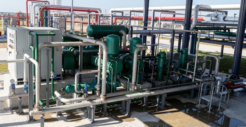
The 4MW series operates on the reciprocating piston principle. A crankshaft driven by a high-voltage induction motor converts rotational motion into the linear reciprocating motion of four pistons arranged in two opposed pairs. As each piston moves through its compression stroke, the CO₂ gas is trapped in the cylinder, reduced in volume, and discharged at elevated pressure. The four cylinders are arranged in two horizontal opposing rows on either side of the crankshaft — the defining characteristic of the four-column opposed-balance design — so that the inertia forces of each cylinder pair cancel out rather than transmit to the foundation.
Four-stage compression: Rather than attempting to achieve the full compression ratio (typically 15:1 to 40:1 from inlet to discharge) in a single cylinder, the gas passes sequentially through four stages of increasing pressure. Between each stage, an interstage cooler removes the heat of compression and an interstage separator removes any condensed liquid before the gas enters the next stage. This multi-stage arrangement keeps discharge temperatures within acceptable limits, improves volumetric efficiency, reduces mechanical loading, and allows the stage pressures to be set to avoid the CO₂ critical point region where liquid formation would cause hydraulic shock.
Principal Structural Components
⚙ Crankshaft & Frame
Forged alloy steel crankshaft with journal hardening. Nodular cast iron or fabricated steel frame with machined bearing housings. Designed to API 618 rod load limits.
🔧 Cylinders & Pistons
High-strength cast iron or ductile iron cylinders. Chrome-plated piston rods for wear resistance. PTFE or cast iron piston rings. Optional stainless steel for corrosive service.
📈 Gas Valves
Ring-plate or poppet valves with stainless steel valve seats and PEEK/PTFE valve elements. Designed for low pressure drop and extended service life exceeding 8,000 hours.
❄ Interstage Cooling
Shell-and-tube heat exchangers between each stage. Interstage separators remove condensate. All cooler tubes in carbon steel (standard) or stainless steel (CO₂ with moisture / H₂S service).
🔐 Sealing System
Pressure packing with PTFE rings and Type C or D double-compartment distance piece per API 618. Crankcase isolated from process gas. Optional nitrogen purge for sour or toxic service.
💻 Control & Monitoring
PLC-based control panel with HMI. Continuous monitoring of vibration, temperature, pressure, rod drop, and lube oil parameters. Safety shutdown on all critical parameters.
Core Advantages of the 4MW Series
⚖
Opposed-Balance Design: Near-Zero Net Vibration
The four-column opposed arrangement cancels primary inertia forces almost completely. Machines can be installed on standard grout-levelled concrete pads without the heavy reinforced foundations required by Z-type or L-type machines of equivalent capacity, reducing civil engineering cost by 30–50%.
📈
API 618 Fifth Edition Full Compliance
All 4MW units are designed to API 618 including Chapter 3 pulsation and mechanical study on request, rod load certification, distance piece classification, and materials specification for process gas service. Full documentation package including MDR available.
🛠
End-to-End In-House Manufacturing
Crankshaft forging, cylinder casting, CNC precision machining, heat treatment, pressure vessel fabrication, and final assembly all performed in our 92,000 m² facility. No dependence on external subcontractors for critical components. Full traceability of materials.
🕑
Extended Maintenance Intervals
Piston ring and packing service life 6,000–10,000 hours. Gas valve replacement intervals 8,000–12,000 hours. Main bearing overhaul 40,000+ hours. Spare parts stocked from our own production, not third-party sourcing, ensuring supply continuity for 20+ year plant operating life.
🏭
Skid-Mounted Factory-Integrated Packages
Complete skid packages available: compressor + motor + interstage coolers + separators + lube oil system + instrumentation + PLC panel pre-assembled, pre-piped, pre-wired and factory-tested on a single baseframe. Site commissioning in days rather than weeks.
🌎
National Standard Drafter Authority
Our engineering team has held primary authorship of the international process compressor design standard applied to medium-pressure CO₂ equipment since 2012, positioning the 4MW series at the forefront of global CO₂ compression engineering.
🔌
Flexible Capacity Control
Suction valve unloaders provide step-wise capacity reduction in 25% increments without stopping the machine. Variable frequency drive (VFD) option available for continuous smooth modulation from 50% to 100% capacity, optimising energy consumption at part-load.
📄
Full FAT Before Shipment
Every 4MW unit undergoes a witnessed full-load mechanical factory acceptance test verifying performance, vibration, rod load, discharge temperature, and safety shutdown function against contractual data sheet values before the unit is released for shipment.
Structure and Material Quality Standards
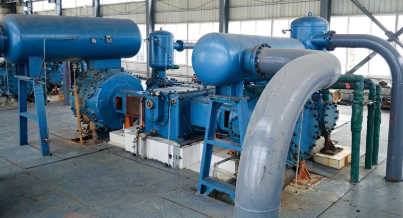
The 4MW series is manufactured to the quality standards demanded by the most stringent industrial process gas applications. Key material and construction specifications include:
| Component |
Material / Standard |
Notes |
| Crankshaft |
42CrMo forged alloy steel, journal induction hardened |
Torsional fatigue tested; UT and MPI inspection |
| Frame / Crosshead Guide |
QT500 nodular cast iron or welded steel |
Stress-relief annealed; precision-bored bearing housings |
| Cylinders |
HT250 grey cast iron; 316L SS for wet/sour CO₂ |
Hydrostatic pressure test at 1.5 × MAWP |
| Piston Rods |
42CrMo steel, hard chrome plated surface |
Roundness ≤ 0.01 mm; Hardness HRC 60–65 |
| Piston Rings & Packing |
PTFE (standard) or PEEK (high-temp / food-grade) |
Service interval 6,000–10,000 h under normal conditions |
| Gas Valves |
316 SS seats; PEEK or PTFE valve elements |
Ring-plate or poppet type; service life 8,000–12,000 h |
| Interstage Coolers |
Carbon steel shell & tube (standard); 316L SS available |
Designed and fabricated under Pressure Vessel License |
| Bearings |
Full-shell aluminium-bronze main bearings |
Forced pressure lubrication; bearing overhaul at 40,000 h |
Typical Application Scenarios
The 4MW series operates in the 3.0–4.0 MPa discharge pressure range, which covers the majority of mid-pressure CO₂ liquefaction, food-grade production, and carbon capture intermediate compression duties. The following applications represent the primary markets served by this product family.
🥥
CO₂ Liquefaction and Food-Grade Carbon Dioxide Production
CO₂ recovered from fermentation, combustion, or purchased as raw gas is compressed to 3.0–4.0 MPa by the 4MW series, then cooled in a condensing system to produce liquid CO₂ at approximately –20°C for storage and distribution. The liquid CO₂ supplies beverage carbonation lines and is further processed into dry ice by expansion and solidification. For food-grade applications, oil-free cylinder specification is mandatory, and the compressor operates as the primary purity control point in the production chain.
Related downstream equipment: The liquid CO₂ produced by this process is also used in injection stretch blow moulding of PET bottles for carbonated beverages. If your facility also produces carbonated drinks packaging, our partner site offers one-step injection stretch blow moulding machines that work in conjunction with CO₂ beverage filling lines — a complementary solution for integrated beverage production facilities.
🌿
Carbon Capture Intermediate Compression (CCS/CCUS)
In post-combustion carbon capture installations, CO₂ is stripped from the amine solvent at near-atmospheric pressure and must be compressed in multiple stages to pipeline transport pressure (8–15 MPa) and then to reservoir injection pressure (15–32 MPa). The 4MW series handles the critical intermediate compression stage, raising the gas from approximately 0.3 MPa to 3.0–4.0 MPa. At this stage the gas is typically still wet and may contain trace SO₂ from the flue gas; 316L stainless steel wetted parts are standard for this service.
⚙️
Chemical Synthesis Feed Gas (Urea, Methanol, Supercritical Extraction)
Urea synthesis requires CO₂ at 13–20 MPa; the 4MW series serves as one of the intermediate stages in the multi-stage urea CO₂ compression train. For methanol synthesis by CO₂ hydrogenation — an emerging Power-to-X pathway — the 4MW series compresses the CO₂ feed from capture system outlet pressure to synthesis reactor pressure of 5–10 MPa. Supercritical CO₂ extraction plants use this series for the high-pressure circulation duty at 7.4–30 MPa, taking advantage of the 4MW’s low vibration to avoid disrupting extraction vessel internals.
🛢️
EOR CO₂ Injection Boost Stage
In enhanced oil recovery projects, CO₂ must be injected at wellhead pressures of 15–32 MPa. The 4MW series is used as the intermediate-pressure boost compressor, raising CO₂ from pipeline receipt pressure (typically 1–3 MPa) to the inlet pressure of the final high-pressure injection stage. This duty benefits directly from the 4MW’s low vibration, as the intermediate-pressure piping network in EOR installations is typically extensive and particularly sensitive to pulsation-induced fatigue.
Selection Guide: How to Specify the Right 4MW Model
To select the correct 4MW model and configuration for your application, please confirm the following parameters before enquiry. Providing complete data at the outset enables our engineering team to deliver an accurate technical proposal without time-consuming back-and-forth.
1
Confirm inlet and discharge pressures with design margins
Provide the actual operating suction pressure (including minimum and maximum variations), the required discharge pressure, and the design margin above maximum operating pressure. For liquefaction duty, include the ambient temperature range to confirm condensing pressure in hot weather conditions.
2
Provide complete inlet gas composition
CO₂ purity, moisture content, H₂S concentration (even trace levels), nitrogen, oxygen, and hydrocarbon impurities. Include the composition variation range — minimum and maximum for each component — not just the design-case composition. This determines wetted-parts materials, seal specification, and distance piece type.
3
Specify required flow rate and turndown range
Provide the design flow rate in Nm³/min or Nm³/h at the stated inlet conditions, and the minimum flow rate the compressor must handle reliably. A turndown below 60% of design capacity typically requires VFD control or additional unloader stages.
4
Confirm oil-free or oil-lubricated cylinder requirement
Oil-free cylinders (PTFE/PEEK rings, Type C or D distance piece) are required for food-grade CO₂, downstream catalyst protection, and any application with an oil content specification below 1 ppm. Oil-lubricated cylinders provide longer ring life and are suitable for EOR, CCS, and chemical synthesis duties.
5
Define installation environment and utility availability
Confirm available cooling water temperature and flow rate, site ambient temperature range, electrical classification zone (ATEX or non-hazardous), available drive voltage (6 kV or 10 kV), and whether a skid-mounted package or loose supply is required. For EPC projects, confirm whether API 618 Chapter 3 pulsation study is included in scope.
4MW Series vs. International Brands: An Objective Comparison
Transparency Notice: The following comparison references Ariel Corporation, Dresser-Rand (Siemens Energy), Neuman & Esser, and Burckhardt Compression by name solely to assist engineers in cross-referencing performance classes during equipment selection. We do not manufacture, sell, or imply any affiliation with these brands. All 4MW compressors are original designs engineered and manufactured by our own team. We do not sell counterfeit or unlicensed copies of any competitor product.
| Comparison Factor |
4MW Series (Our Make) |
Ariel JGC / JGB |
Dresser-Rand HOSS |
Burckhardt Laby |
| API 618 Compliance |
✓ Full |
✓ Full |
✓ Full |
✓ Full |
| Ex-works Price (85–150 m³/min) |
Competitive — typically 30–50% below European OEM |
High (USD reference) |
High (EUR reference) |
Premium (CHF reference) |
| Lead Time (standard order) |
5–8 months |
8–14 months |
10–16 months |
10–18 months |
| Spare Parts Availability |
In-house production; rapid dispatch |
OEM only; import lead times |
OEM only; high cost |
OEM only; premium pricing |
| Local Service Support |
Russia / CIS on-site commissioning; global service network |
Global network; premium rates |
Regional offices |
Regional offices |
| Customisation Flexibility |
High — in-house engineering team |
Standard product range |
Moderate |
Moderate |
| Factory Acceptance Test |
✓ Full-load mechanical FAT standard |
✓ Standard |
✓ Standard |
✓ Standard |
The 4MW series offers comparable mechanical performance to the referenced international brands at significantly lower capital cost and lead time — a meaningful advantage in project economics, particularly for markets in Asia, the Middle East, and Eastern Europe where CO₂ compression projects are accelerating due to CCS policy commitments and food-grade CO₂ demand growth. We do not claim that our machine is superior in every respect to every competitor; we claim that it is a technically credible, API 618-compliant alternative that should be considered in any competitive tender.
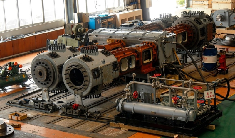
Full-load factory acceptance test (FAT) in progress — every 4MW unit is tested at design operating conditions before shipment, with performance data documented against the contractual data sheet
Frequently Asked Questions — 4MW Series CO₂ Compressor
Q1: What is the difference between the 4MW-85/40(30) and 4MW-85/30 designation?
The notation 40(30) in the model number indicates a dual-pressure design: the compressor can be configured to deliver at 4.0 MPa maximum or 3.0 MPa standard operating pressure. The cylinder bore sizing accounts for both operating conditions, allowing the same physical machine to be used in either configuration by changing the staging arrangement or adjusting valve clearances. This dual-pressure capability reduces the number of machine types required to cover a broad range of process pressures and is a standard feature across the 4MW series.
Q2: Can the 4MW series handle wet CO₂ with high moisture content?
Yes, provided the materials specification is upgraded for wet service. For CO₂ with free water or moisture above the dew point at any stage of compression, cylinder liners, heads, interstage piping, and cooler tubes are specified in 316L stainless steel or duplex stainless steel to resist carbonic acid corrosion (formed when CO₂ dissolves in water). Interstage separators are sized for complete liquid knockout at all anticipated operating conditions, and high-level liquid alarms with automatic shutdown are standard on the wet-service configuration. Upstream dehydration to a dew point of –20°C or lower is always recommended as the primary protection measure.
Q3: Is the 4MW series suitable for food-grade CO₂ production?
Yes. For food-grade CO₂ and beverage carbonation applications, the 4MW series is supplied with oil-free cylinder configuration: PTFE or PEEK piston rings, PTFE pressure packing, and a Type C or D double-compartment distance piece isolating the crankcase lubrication system from the compression circuit. This design ensures zero oil contamination of the CO₂ gas stream, meeting the ISBT food-grade CO₂ specification of total oil content below 0.1 ppm. A gas purity analysis at the compressor outlet can be included in the factory acceptance test on request.
Q4: How does the opposed-balance design reduce foundation requirements?
In a reciprocating compressor, pistons moving back and forth generate unbalanced inertia forces that are transmitted to the foundation as vibration. In a four-column opposed-balance arrangement, cylinders are paired on opposite sides of the crankshaft so that one piston is moving toward the crankshaft while the opposing piston moves away from it. The resulting inertia forces point in opposite directions and cancel almost completely. The residual unbalanced force (primarily secondary inertia from the difference in piston mass and connecting rod geometry) is typically 5–15% of the equivalent value for a single-column or Z-type machine of the same capacity, allowing installation on standard concrete pads rather than heavy isolated foundations.
Q5: What is the recommended maintenance interval for the 4MW series?
Under normal operating conditions with clean, dry CO₂ and proper lubrication: piston rings and packing rings should be inspected at 4,000 hours and replaced at 6,000–8,000 hours; gas valve elements should be replaced at 8,000–10,000 hours; piston rod surface inspection and chrome layer measurement annually; main bearing and connecting rod bearing overhaul at 30,000–40,000 hours. These intervals are extended compared to lower-quality machines because of our forged steel crankshaft, precision-machined bearing housings, and quality PTFE ring materials. Actual intervals should be adjusted based on operating data and condition monitoring readings.
Q6: Can a skid-mounted package be supplied, and what does it include?
Yes, complete skid-mounted packages are available and are the preferred supply format for remote sites and projects where minimising on-site installation time is a priority. A standard 4MW skid package includes: the main compressor unit on a steel baseframe, the drive motor, suction scrubber and knockout vessel, interstage coolers (shell-and-tube), interstage separators, discharge pulsation dampeners, the lube oil system (reservoir, pump, cooler, filter), an instrument air/nitrogen purge system for distance pieces, all interconnecting piping pre-fabricated and pressure-tested, and a local control panel with PLC, HMI, process sensors, and safety shutdown logic. The complete package is factory-assembled and tested before shipment.
Q7: Does the 4MW series require a pulsation study per API 618?
API 618 Chapter 3 pulsation and mechanical study is available as an option and is mandatory for process applications above 5 MPa discharge pressure or where the compressor is on a critical process path. The study digitally simulates the acoustic behaviour of the complete piping system from compressor suction to the downstream process, identifies resonance risks, and specifies any required pulsation dampeners or piping modifications. For EOR, CCS, and chemical plant applications, we recommend including the Chapter 3 study in the scope from the outset. For lower-pressure CO₂ liquefaction duty, a simplified Chapter 2 study is typically adequate.
Q8: What is the typical lead time from order to delivery?
Standard lead time for a 4MW series compressor is 5–8 months from receipt of confirmed purchase order and signed-off technical data sheet. This includes engineering design and approval, procurement of long-lead materials (forged crankshaft, special alloy components), manufacturing, assembly, and factory acceptance test. For urgent projects, accelerated delivery in 4–5 months may be achievable for standard configurations subject to production schedule availability at the time of order. Custom configurations or special materials specifications may require additional time. Please contact our sales engineering team with your required delivery date at the enquiry stage.
Q9: Can the 4MW series be supplied with ATEX-rated electrical equipment?
Yes. For installations in hazardous area zones where CO₂ or associated flammable gases require ATEX or IECEx zone classification, all electrical equipment on the compressor package can be supplied with appropriate hazardous area certification. This includes the drive motor, control panel, junction boxes, solenoid valves, and all sensors and instruments. The applicable hazardous area zone and equipment group must be specified by the client’s electrical engineer; we procure and certify accordingly. ATEX certification adds to the equipment cost and may extend the lead time by 4–8 weeks depending on motor size.
Q10: Are spare parts available for the full life of the plant?
Yes. All spare parts for the 4MW series — including piston rings, packing rings, gas valves and valve elements, piston rods, bearings, seals, and gaskets — are manufactured in-house from our own production, not sourced from third-party suppliers. This means we can commit to spare parts supply for the full design life of the compressor (typically 20–30 years) without dependency on external supply chains. At the time of order, we provide a recommended commissioning spare parts list, a two-year operating stock list, and a major overhaul spare parts list. Critical consumables can be held in warehouse stock at our facility for rapid dispatch on customer request.
Partner With Us: Request a Technical Proposal
Our company has been manufacturing process gas compression equipment for industrial clients across 40+ countries for over 70 years, operating from our facility in Russia. As engineers who have held primary authorship of the international medium-pressure CO₂ compressor design standard since 2012, we bring a level of process engineering depth to every project that is rare outside of the largest European OEMs — at significantly lower capital cost and faster delivery.
Whether you are specifying a new CO₂ liquefaction plant, replacing an ageing Ariel or Dresser-Rand unit, or engineering a carbon capture compression train, our engineering team is available to review your process conditions, recommend the right 4MW configuration, and provide a detailed technical and commercial proposal without obligation.
4MW Series CO₂ Compressor — Engineering Enquiry
Ready to Discuss Your CO₂ Compression Project?
Send us your process data sheet and we will return a technical recommendation within 48 hours. All enquiries are handled by qualified process engineers, not sales agents.
What to Include in Your Enquiry
✓ Required flow rate (Nm³/min or Nm³/h)
✓ Inlet and discharge pressures
✓ CO₂ gas composition and purity
✓ Oil-free or oil-lubricated requirement
✓ Cooling water availability
✓ Site electrical classification
✓ Required delivery date
✓ Skid package or loose supply